Dense phase pump for dry particulate material

a technology pump, which is applied in the direction of pump, positive displacement liquid engine, liquid fuel engine, etc., can solve the problems of difficult cleaning, difficult cleaning, and difficult cleaning of dry particulate material application, so as to facilitate cleaning and service, easy replacement or service, and enhanced cleanability and serviceability

Inactive Publication Date: 2005-07-21
NORDSON CORP
View PDF41 Cites 55 Cited by
  • Summary
  • Abstract
  • Description
  • Claims
  • Application Information

AI Technical Summary

Benefits of technology

[0014] In accordance with another aspect of the invention, cleanability and serviceability are facilitated by providing replaceable wear parts that have interior surfaces that form part of the material flow path in the pump. On one embodiment, the wear parts are realized in the form of Y-blocks that are releasably retained in a solid body for easy access and replacement.
[0015] In accordance with a further aspect of the invention, cleanability and serviceability are further enhanced by a modular pump design. In one embodiment, a modular dense phase pump is provided that is characterized by a number of modular elements such as a manifold body, a valve body and one or more material flow path bodies that include one or more wear surfaces. The modular elements are secured together such as by bolts. By locating the wear parts in separate modular elements, they can be easily replaced or serviced when normal purging alone is not sufficient to clean the surfaces. In accordance with another aspect of the invention, a modular construction is contemplated by which all pneumatic energy is supplied to the pump via a manifold body. In one embodiment, the manifold body provides pneumatic ports on a single surface to receive pressurized air from corresponding ports formed in a single surface of a supply manifold. The manifold body also optionally accommodates a purge function. In accordance with still another aspect of the invention, pressurized air needed for pneumatic valves in the pump is routed internally to the valve body from the manifold body.
[0016] In further accordance with another aspect of the invention, interior surface areas are reduced by designing the pump to operate with high material density low air volume material feed. In the context of a powder coating material pump, high density means that the powder supplied by the pump to an applicator has a substantially reduced amount of entrainment or flow air in the powder flow as compared to conventional low density or dilute powder flow systems. Low air volume simply refers to the use of less volume of flow air needed to move or transfer powder due to its higher density in the powder flow.
[0017] By removing a substantial amount of the air in the powder flow, the associated conduits, such as the powder path through the pump, a powder feed hose and a powder feed tube, can be substantially r

Problems solved by technology

The application of dry particulate material is especially challenging on a number of different levels.
Wear items that have surfaces exposed to material impact, for example a spray nozzle in a typical powder spray gun, can be difficult to clean due to impact fusion of the powder on the wear surfaces.
Pumps also tend to have one or more wear surfaces that are difficult to clean by purging due to impact fusion.
Conventional venturi pumps can be purged in the direction of the gun, but are difficult to

Method used


Image

  • Dense phase pump for dry particulate material
  • Dense phase pump for dry particulate material
  • Dense phase pump for dry particulate material

Examples


Embodiment Construction

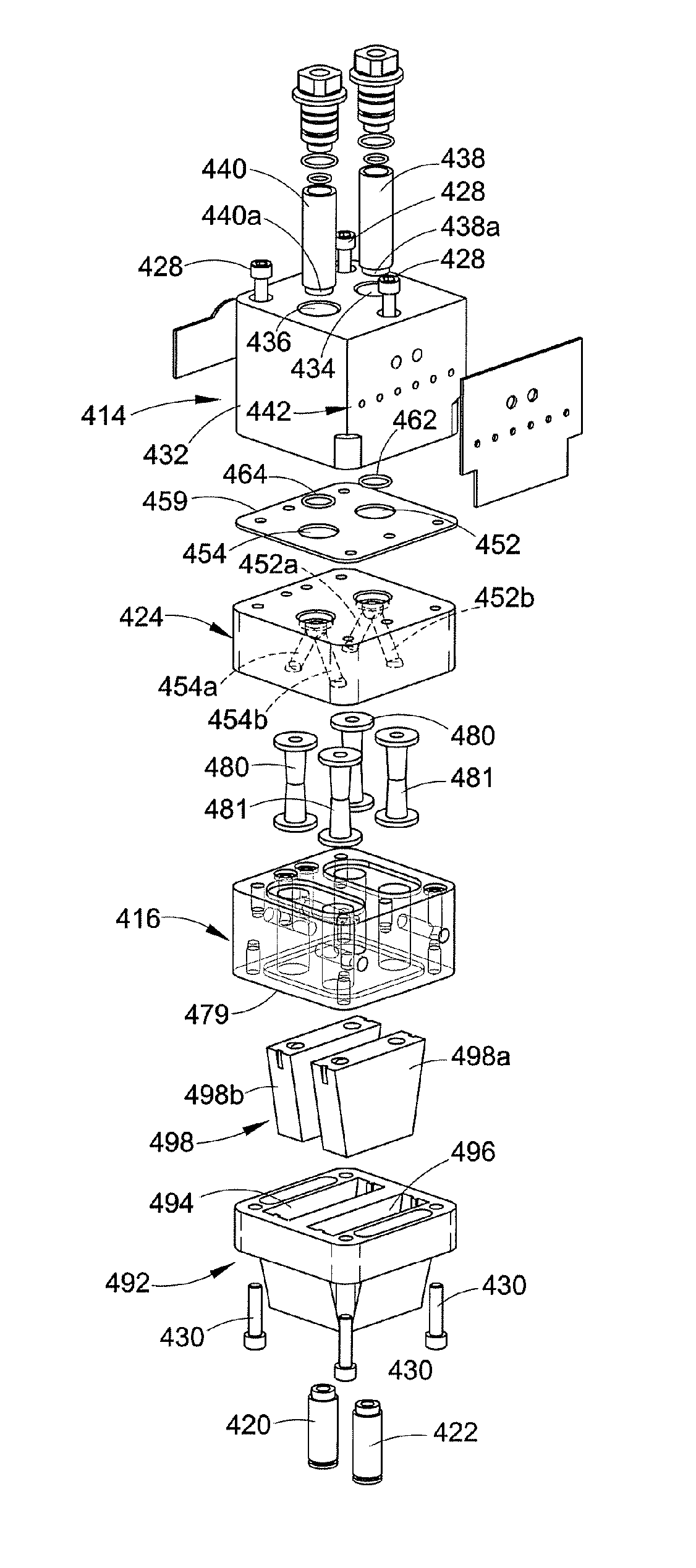
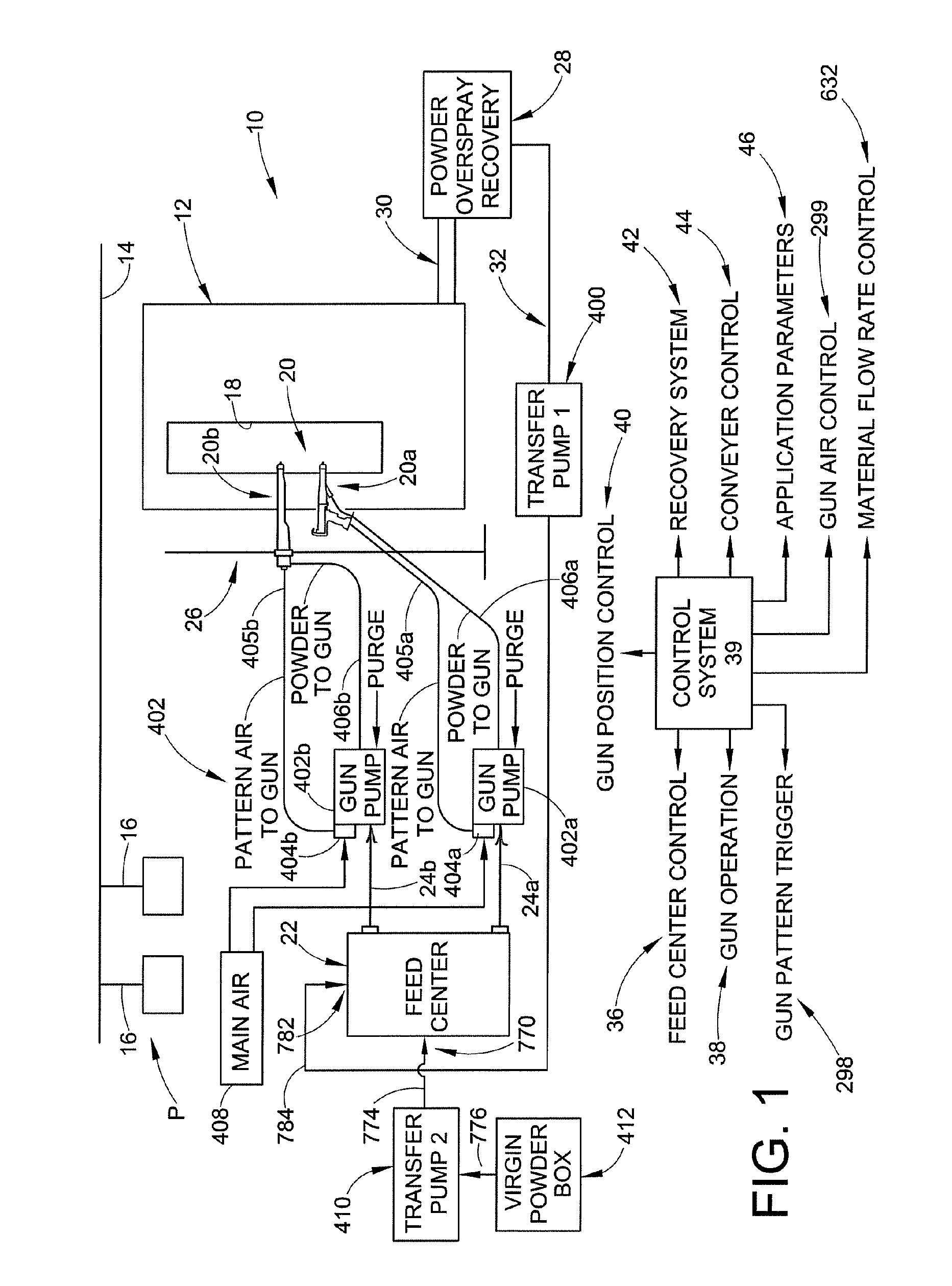
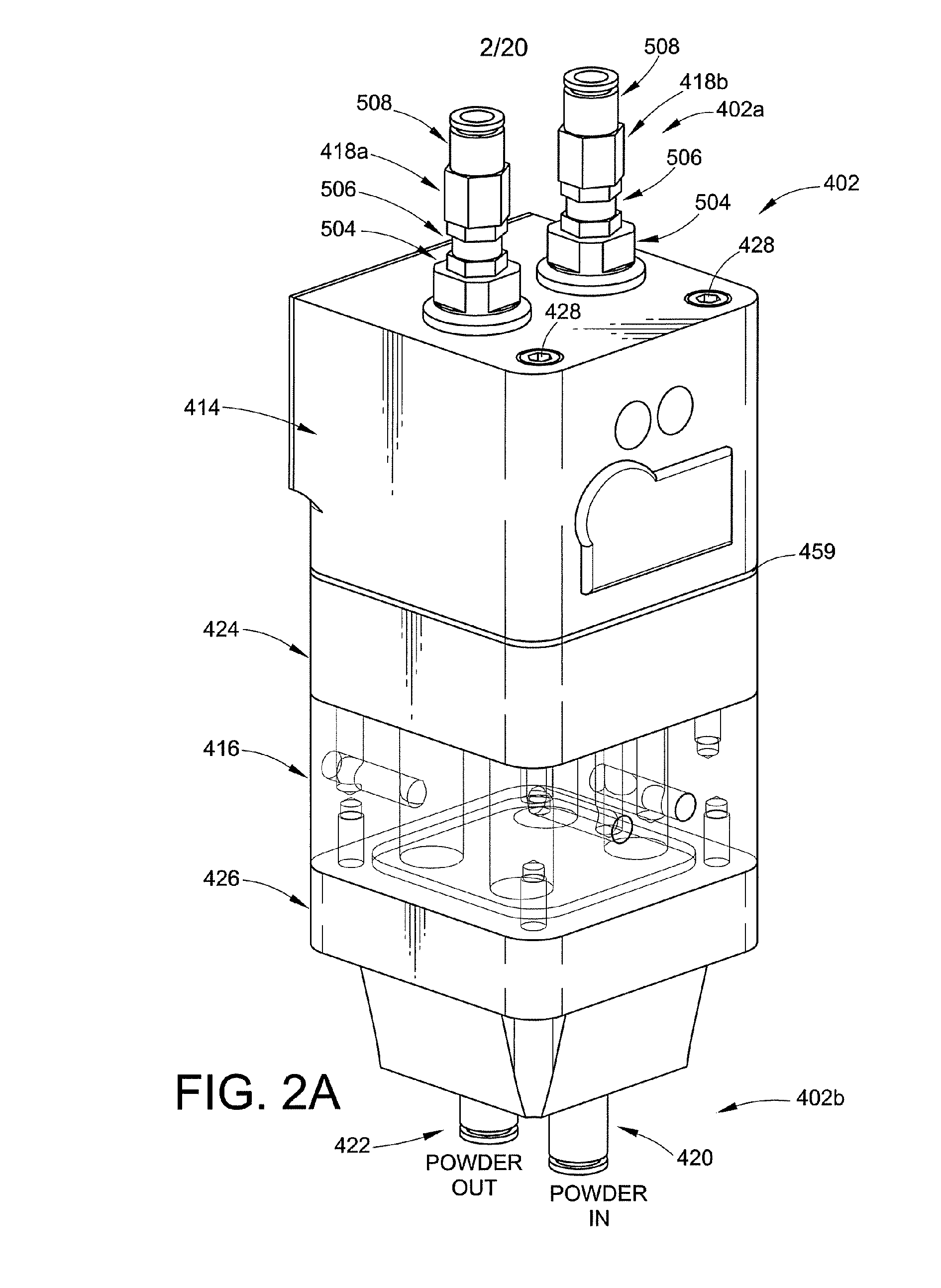
[0036] The invention contemplates a number of new aspects for a dense phase pump for particulate material. The pump may be used in combination with any number or type of spray applicator devices or spray guns and material supply.

[0037] By “dense phase” is meant that the air present in the particulate flow is about the same as the amount of air used to fluidize the material at the supply such as a feed hopper. As used herein, “dense phase” and ”high density” are used to convey the same idea of a low air volume mode of material flow in a pneumatic conveying system where not all of the material particles are carried in suspension. In such a dense phase system, the material is forced along a flow path by significantly less air volume as compared to a conventional dilute phase system, with the material flowing more in the nature of plugs that push each other along the passage, somewhat analogous to pushing the plugs as a piston through the passage. With smaller cross-sectional passages ...


PUM


Abstract

A dense phase pump for particulate material includes a pump chamber wherein material flows into the pump chamber under negative pressure and flows out of the pump chamber under positive pressure. A plurality of pinch valves are provided to control flow of material into and out of the pump chamber. The pinch valves are operated independent of each other and of the pump cycle rate. A modular design of the pump is provided.

Description

RELATED APPLICATIONS [0001] This application claims the benefit of pending U.S. provisional patent application Ser. No. 60 / 524,459 filed on Nov. 24, 2003, for PINCH PUMP WITH VACUUM TUBE the entire disclosure of which is fully incorporated herein by reference.TECHNICAL FIELD OF THE INVENTION [0002] The invention relates generally to material application systems, for example but not limited to powder coating material application systems. More particularly, the invention relates to a pump that reduces cleaning time, color change time and improves convenience of use. BACKGROUND OF THE INVENTION [0003] Material application systems are used to apply one or more materials in one or more layers to an object. General examples are powder coating systems, other particulate material application systems such as may be used in the food processing and chemical industries. These are but a few examples of a wide and numerous variety of systems used to apply particulate materials to an object. [0004...

Claims


Application Information

Patent Timeline
IPC IPC(8): B05B7/14B05B15/12
CPCB05B7/1459F04F5/48B05B15/1229B05B14/48
Inventor FULKERSON, TERRENCE M.BEUK, EDWIN JEROENKLEINEIDAM, ULFKLEINEIDAM, ANDREAS
Owner NORDSON CORP
Why Eureka
Try Eureka