Targeted biopsy delivery system

a biopsy and delivery system technology, applied in the field of targeted biopsy delivery system, can solve the problems of difficulty in preciseness, need for additional samples to be taken, and difficulty in accurate knowledge of physicians, and achieve the effect of quick sequence extension and quick movemen

Inactive Publication Date: 2005-07-21
TAYLOR JAMES D +2
View PDF20 Cites 144 Cited by
  • Summary
  • Abstract
  • Description
  • Claims
  • Application Information

AI Technical Summary

Benefits of technology

[0027] Once the biopsy is planned, the physician initiates the biopsy. All of the needle paths for a given longitudinal image are displayed on the ultrasound monitor. The display shows the coordinates of the planned needle paths which correlate to the positional setting of the redirecting needle guide. The physician then advances and / or rotates the redirecting needle guide to the correlating coordinates for the first planned needle path. The physician then inserts a flexible biopsy needle kit into the redirecting needle guide's needle insertion point. The needle set is advanced by hand through the needle set channel, including through the redirecting curve within the needle guide. This redirecting curve causes the needle to exit the needle guide, within the rectum of the patient, at an angle relative to the transrectal probe. The physician pushes the needle guide through the tissue of the rectal wall and into the prostate, monitoring the progress of the needle on the ultrasound system and insuring that the actual path of the needle matches the planned needle path being projected on the image. When the biopsy needle set has achieved the correct depth of penetration, the physician uses a standard biopsy firing gun to “fire” the needle set, causing the stylet and cannula to quickly extend in sequence, cutting and capturing a slice of prostate tissue in the specimen notch of the needle set. Because the specimen notch is substantially longer than in standard biopsy needles and the cannula body is flexible, the needle set is very flexible and able to be fired even though bent. The specimen notch is extended to the curved portion of the needle set within the redirecting needle set guide, allowing the stylet to be quickly moved in reference to the cannula without binding. With the needle still in the prostate, the physician saves the ultrasound image(s) on the computer program, creating a permanent record of the biopsy tissue location. The physician then removes the biopsy needle with captured tissue sample. Once removed, the cannula is retracted from the stylet, allowing the tissue sample to be placed into a tissue specimen dish. The physician then advances or moves the redirecting biopsy needle guide to the next planned needle path location, and repeats the procedure.

Problems solved by technology

Because the probe must be physically moved about within the rectum by hand to identify and target the different areas of the prostate, it is difficult for physicians to precisely targeted biopsy sample locations, often causing the need for additional samples to be taken.
Further, if a sample seems to confirm cancer, it is difficult for the physician to accurately know where in the prostate the sample was taken from, and so difficult to re-biopsy the same tissue location to confirm the cancer.
However, all of these inventions suffer from a number of disadvantages.
All require specialized equipment, and do not make use of existing ultrasound systems and technology.
All require the movement of the imaging device, making it more difficult to plan and target areas of the prostate for biopsy.
Further, the flexible biopsy needles called out either require heating or additional force to cause them to fire, and are impractical for use with established prostate biopsy procedures and existing biopsy needle set firing devices.

Method used


Image

  • Targeted biopsy delivery system
  • Targeted biopsy delivery system
  • Targeted biopsy delivery system

Examples


Embodiment Construction

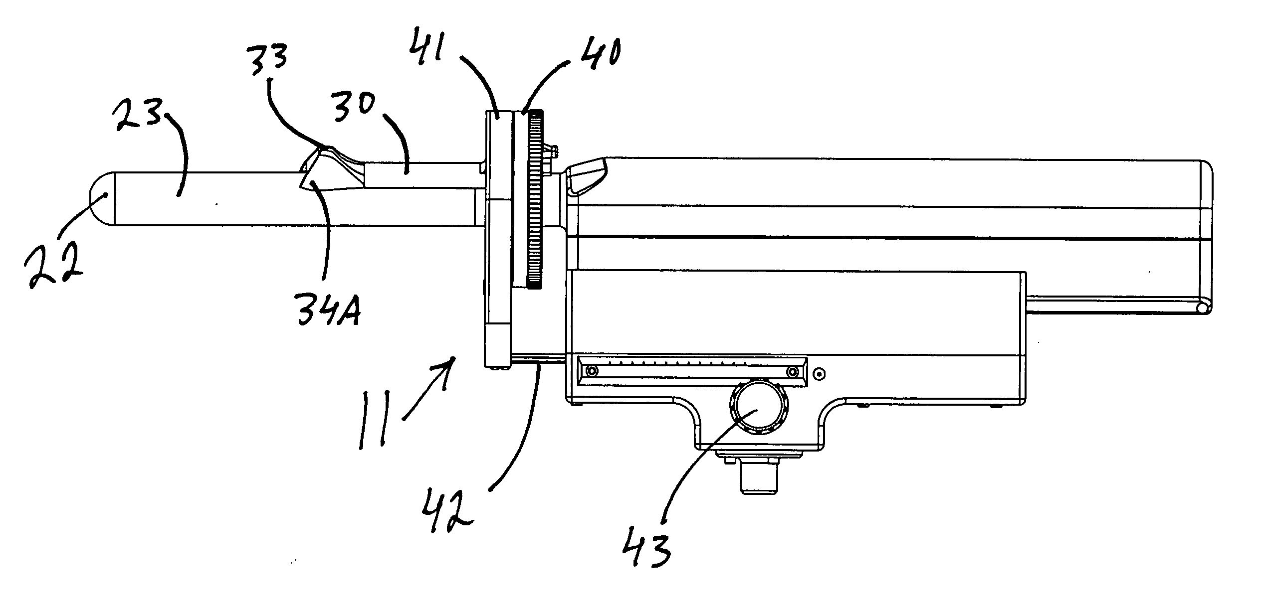
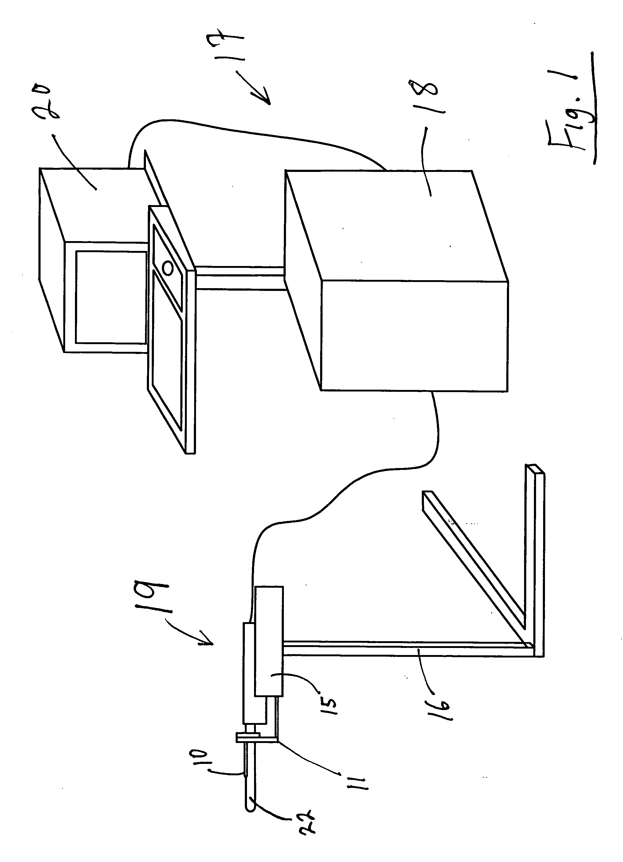
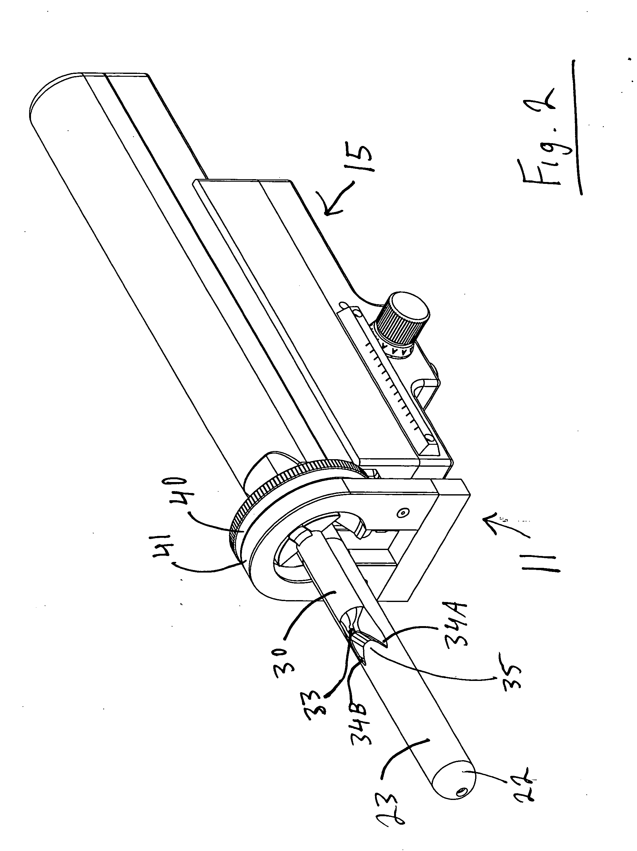
[0113] As seen in FIG. 1, the targeted biopsy system is comprised of a redirecting guide 10, positioning assembly 11, targeting software system 12 (loaded on CPU 18) and flexible needle set 13 (best seen in FIG. 20). The positioning assembly 11 is affixed to cradle 15, which is a part of stepper and stabilizer 16. Working in conjunction with the targeted biopsy system is ultrasound system 17, which is comprised of ultrasound system CPU 18, side view transrectal probe 19 and monitor 20. Side view transrectal probe is comprised of probe tip 22 and probe imaging window 23. As seen in FIGS. 2 and 7, the redirecting guide 10 consists of guide body 30, needle set channel 31, needle set insertion point 32, and needle set exit point 33, front body guide extensions 34A and 34B, imaging cutout 35. As seen in FIG. 10, needle set channel 31 may be provided with enlarged bend channel 37. As seen in FIG. 8, the redirecting guide 10 may be provided with insertable metal tube 38. In an alternative ...


PUM


Abstract

This invention relates generally to the targeting and biopsy of tissue for medical purposes, and more particularly to a targeted biopsy system which allows planning of tissue to be sampled, targeting of specific areas of tissue in reference to the plan, capturing the tissue sample and recording the source location of the tissue sample, particularly for use in collecting tissue samples from the prostate gland. A further purpose of this invention is to provide a targeted treatment system which allows planning of tissue to be treated, targeting of specific areas of tissue in reference to the plan, and delivering the treatment to the targeted tissue.

Description

CROSS REFERENCE TO RELATED APPLICATION [0001] This nonprovisional patent application claims priority to the provisional patent application having Ser. No. 60 / 494,910, which was filed on Aug. 13, 2003.BACKGROUND OF THE INVENTION [0002] Prostate health is a significant concern for men over the age of fifty. If prostate cancer is suspected from either a physical examination or because of a Prostate Specific Antigens test, a biopsy is performed to collect tissue samples from the prostate for evaluation by a pathologist. Prostate tumors are small growths scattered about the prostate. For this reason, a physician will take multiple tissue samples from different areas of the prostate, typically between 9 and 18 samples. [0003] The normal procedure for obtaining biopsy samples with ultrasound guidance is called Transrectal Ultrasound (TRUS) Guided Prostate Biopsy. An end-fire ultrasound probe is used, which generates a pie-shaped image plane. Some end-fire probes are manufactured with a bio...

Claims


Application Information

Patent Timeline
Patent Type & Authority Applications(United States)
IPC IPC(8): A61B10/00A61B10/02A61B17/00A61B17/32A61B17/34A61B19/00
CPCA61B10/0241A61B2019/5276A61B10/0275A61B17/3403A61B17/3421A61B19/50A61B2010/0225A61B2017/00199A61B2017/00274A61B2017/00862A61B2017/00867A61B2017/3411A61B2017/3413A61B2018/00547A61B2019/507A61B10/0266A61B34/10A61B2034/107A61B2090/378A61B10/02A61B10/06A61B17/32
Inventor TAYLOR, JAMES D.OLSON, BRUCELEWIS, STEPHEN
Owner TAYLOR JAMES D
Why Eureka
Try Eureka