
Optical rosa for long reach optical transceiver

a long-range, optical transceiver technology, applied in the field of optical communication systems, can solve the problems of large active area of high-speed apd, high cost of apd-based rosa, etc., and achieve the effect of low cost and high sensitivity

Active Publication Date: 2005-07-28
LUMENTUM FIBER OPTICS INC
View PDF8 Cites 23 Cited by
  • Summary
  • Abstract
  • Description
  • Claims
  • Application Information

AI Technical Summary

Benefits of technology

[0007] In accordance with embodiments of the present invention, a receiver optical sub assembly (ROSA) is presented that focuses received light onto a small active area, for example that of the active surface of an avalanche photo-diode (APD). Some embodiments of the resulting ROSA structure architecture, then, can achieve high sensitivity with low cost components and assembly processes.
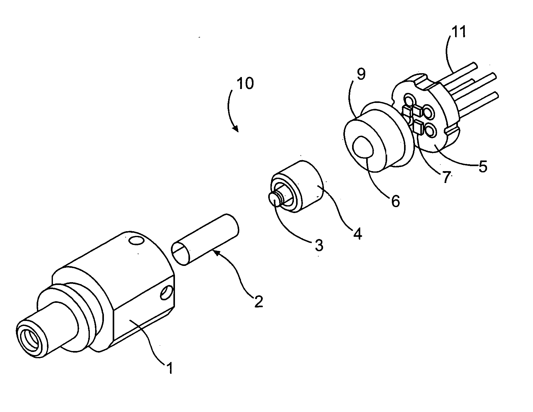
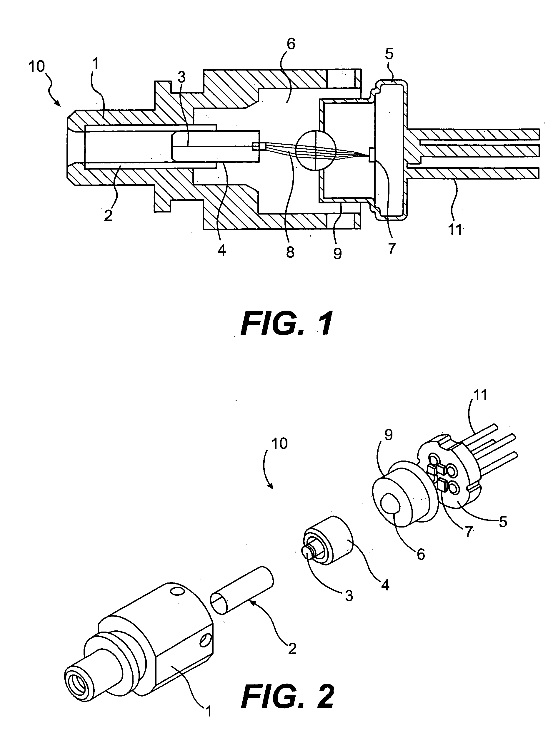
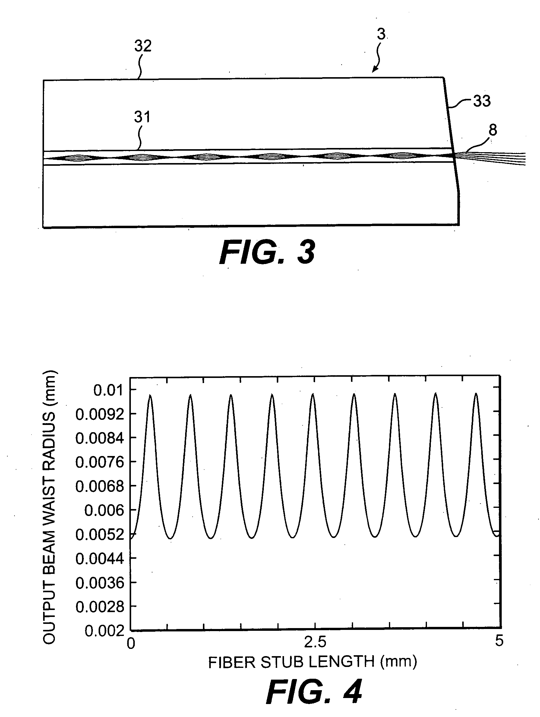
[0011] In some embodiments of the invention, the ROSA accepts an optical beam from a single-mode optical fiber into a multimode fiber stub. The beam divergent angle and waist size are converted in the multimode fiber stub to allow the use of low-cost ball lenses in focusing. The multimode fiber stub acts as a gradient index (GRIN) lens. In some embodiments, the length of the multimode fiber stub is optimized to modify the parameters of its output beam. The optimized beam size and divergent angle can be utilizied to provide a small spot size focused on the APD active area. In some embodiments of the invention, sufficient alignment tolerances are achieved so that the use of low cost epoxy processes for assembly of the ROSA can be used to assemble the ROSA.
[0012] Further, in some embodiments a high return loss characteristic can be achieved. In some embodiments, the end surface of the fiber stub can be angle polished to eliminate or reduce the reflection from the fiber-air interface back to the fiber. The detector chip can also be positioned with an offset such that the incident beam can be incident on the APD chip at an oblique angle to minimize the amount of light reflected from the detector chip back into the optical fiber.

Problems solved by technology

However, the active area of a high-speed APD is generally limited in size.
The cost of the APD-based ROSA, then, can be very high due to the intrinsic high cost of the APD, as well as the more expensive optical lenses required in the lens system and very involved assembly process.

Method used


Image

  • Optical rosa for long reach optical transceiver
  • Optical rosa for long reach optical transceiver
  • Optical rosa for long reach optical transceiver

Examples


Embodiment Construction

[0020]FIG. 1 illustrates a cross sectional diagram of an embodiment of a receiver optical sub assembly (ROSA) 10 according to the present invention. ROSA 10 includes a multimode fiber stub 3 and a lens system 6 optically coupled to focus light onto a detector chip 7. Detector chip 7 can be any sufficiently sensitive and stable photo detector, for example an avalanche photodiode. Other examples of detectors that can be utilized, include PIN diodes. As was discussed above, an avalanche photodiode (APD) can meet high requirements in sensitivity and noise. However, an APD can have a small active area, which requires more exacting alignment tolerances of the components of ROSA 10.

[0021] In some embodiments of the invention, ROSA 10 includes a stub holder 4 that interfaces with a receptacle 1 to hold multimode fiber stub 3. In some embodiments, a portion of multimode fiber stub 3 can be pressed into stub holder 4 and stub holder 4 can be pressed into receptacle 1 such that an optical axi...


PUM


Abstract

A receiver optical amplifier assembly (ROSA) is disclosed that provides for greater tolerances in alignment. The ROSA includes a multimode fiber stub to receive a light beam from a single mode optical fiber. The light beam from the multimode fiber stub is focused by a lens system onto the active area of an optical detector chip. The multimode fiber stub acts as a GRIN lens and allows for optimization of the spot size on the active area. Additionally, in some embodiments the return loss characteristics of the ROSA can be greatly improved by including an angled surface on the multimode fiber stub and moving the active area of the optical detector chip off-axis to compensate.

Description

BACKGROUND [0001] 1. Field of the Invention [0002] The present invention relates generally to optical communication systems and, particularly to small form factor high-speed optical transceivers with high sensitivity receivers. [0003] 2. Discussion of Related Art [0004] There is currently a demand for high-speed, long-distance, cost-effective, and highly integrated optical transceiver systems. Therefore, optical receiver systems that are high performance, low cost, and are of small size are desired. For short reach and medium distance transmission, a PIN photo detector based receiver can be used. For long reach transceivers (e.g., for transmission over tens of kilometers), however, high sensitivity receivers are required to compensate for the optical signal loss due to long optical fibers. In long reach systems, then, an avalanche photodiode (APD) can be utilized instead of a PIN photodiode because of its higher sensitivity and lower noise characteristics. [0005] However, the active...

Claims


Application Information

Patent Timeline
IPC IPC(8): G02B6/42
CPCG02B6/4206G02B6/4292G02B6/421G02B6/4207
Inventor VANNIASINKAM, JOSEPH INDHIRANZHU, LIJUN
Owner LUMENTUM FIBER OPTICS INC
Learn More