Formation of a tantalum-nitride layer

a technology of tantalum nitride and barrier layer, applied in the field of formation, can solve the problems of high chlorine content, inability to meet the requirements of chemical vapor deposition,

Inactive Publication Date: 2005-07-28
APPLIED MATERIALS INC
View PDF99 Cites 62 Cited by
  • Summary
  • Abstract
  • Description
  • Claims
  • Application Information

AI Technical Summary

Benefits of technology

[0015] In another aspect, a method of film deposition for integrated circuit fabrication includes forming a tantalum-containing layer with a sheet resistance of about 1,200 μΩ-cm or less by a plasma annealing process on a tantalum nitride layer deposited by an atomic layer deposition process on a substrate.
[0016] These and other aspects of the present invention will be more apparent from the following description.

Problems solved by technology

For sub half-micron (0.5 μm) semiconductor devices, microscopic reaction at an interface between metal and barrier layers can cause degradation of integrated circuits, including but not limited to increased electrical resistance of such metal layers.
However, when Cl-based chemistries are used to form boride barrier layers, reliability problems can occur.
A high chlorine content is undesirable because migrating chlorine from a boride barrier layer into adjacent interconnection layer may increase contact resistance of such interconnection layer and potentially change one or more characteristics of integrated circuits made therewith.

Method used


Image

  • Formation of a tantalum-nitride layer
  • Formation of a tantalum-nitride layer
  • Formation of a tantalum-nitride layer

Examples


Embodiment Construction

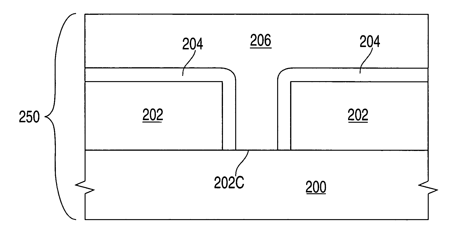
[0022]FIG. 1 depicts a schematic illustration of a wafer processing system 10 that can be used to form one or more tantalum-nitride barrier layers in accordance with aspects of the present invention described herein. System 10 comprises process chamber 100, gas panel 130, control unit 110, along with other hardware components such as power supply 106 and vacuum pump 102. For purposes of clarity, salient features of process chamber 100 are briefly described below.

Process Chamber

[0023] Process chamber 100 generally houses a support pedestal 150, which is used to support a substrate such as a semiconductor wafer 190 within process chamber 100. Depending on process requirements, semiconductor wafer 190 can be heated to some desired temperature or within some desired temperature range prior to layer formation using heater 170.

[0024] In chamber 100, wafer support pedestal 150 is heated by an embedded heating element 170. For example, pedestal 150 may be resistively heated by applying ...


PUM

PropertyMeasurementUnit
temperatureaaaaaaaaaa
pressureaaaaaaaaaa
temperatureaaaaaaaaaa

Abstract

A method of forming a tantalum nitride layer for integrated circuit fabrication is disclosed. In one embodiment, the method includes forming a tantalum nitride layer by chemisorbing a tantalum precursor and a nitrogen precursor on a substrate disposed in a process chamber. A nitrogen concentration of the tantalum nitride layer is reduced by exposing the substrate to a plasma annealing process. A metal-containing layer is then deposited on the tantalum nitride layer by a deposition process.

Description

CROSS-REFERENCE TO RELATED APPLICATIONS [0001] This application is a continuation of co-pending U.S. patent application Ser. No. 09 / 776,329, filed Feb. 2, 2001, which is hereby incorporated by reference.BACKGROUND OF THE INVENTION [0002] 1. Field of the Invention [0003] The present invention relates to formation of one or more barrier layers and, more particularly to one or more barrier layers formed using chemisorption techniques. [0004] 2. Description of the Related Art [0005] In manufacturing integrated circuits, one or more barrier layers are often used to inhibit diffusion of one or more materials in metal layers, as well as other impurities from intermediate dielectric layers, into elements underlying such barrier layers, such as transistor gates, capacitor dielectrics, transistor wells, transistor channels, electrical barrier regions, interconnects, among other known elements of integrated circuits. [0006] Though a barrier layer may limit to prevent migration of unwanted mate...

Claims


Application Information

Patent Timeline
Patent Type & Authority Applications(United States)
IPC IPC(8): C23C16/34C23C16/44C23C16/455C23C16/56H01L21/285H01L21/768
CPCC23C16/34C23C16/4554C23C16/45553H01L21/76862H01L21/28562H01L21/28568H01L21/76844C23C16/56
Inventor SEUTTER, SEAN M.YANG, MICHAEL X.XI, MING
Owner APPLIED MATERIALS INC
Why Eureka
Try Eureka