Soft tissue defect repair device

Active Publication Date: 2005-07-28
WL GORE & ASSOC INC
View PDF36 Cites 41 Cited by
  • Summary
  • Abstract
  • Description
  • Claims
  • Application Information

AI Technical Summary

Benefits of technology

[0016] If desired, the length of the substantially hollo

Problems solved by technology

However, there are reported cases of devices of this type having migrated from the site of the defect.
Further, the mesh filler material is often not adequate to provide

Method used


Image

  • Soft tissue defect repair device
  • Soft tissue defect repair device
  • Soft tissue defect repair device

Examples


example 1

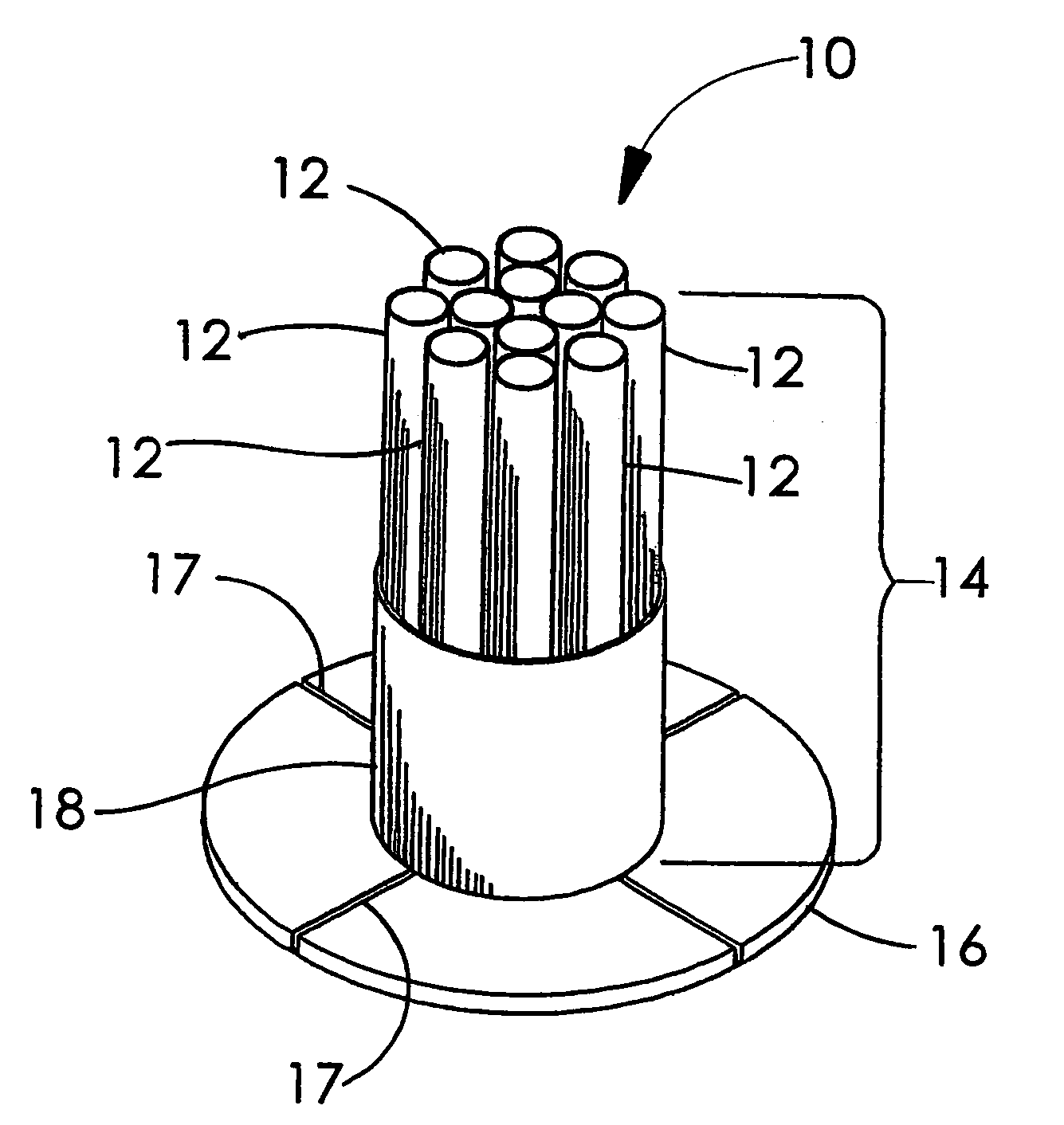
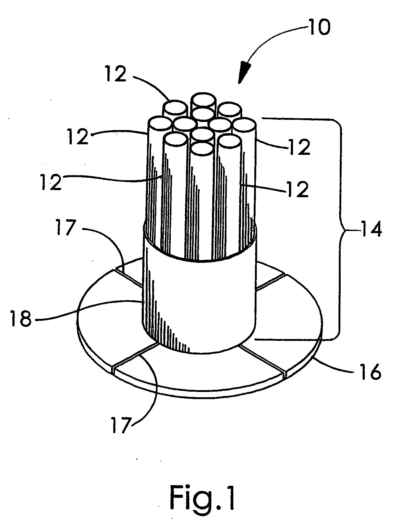
[0056] This example describes the construction of a multiple tube hernia repair device of the present invention as shown in FIG. 1. A triblock copolymer of 67% / 33% PGA:TMC (w / w) was acquired from US Surgical (Norwalk Conn.) and formed into a self-cohering web as generally taught by Hayes in U.S. Pat. No. 6,165,217. Sheets of this copolymer web material were formed into the 3 component types used in the construction of this device.

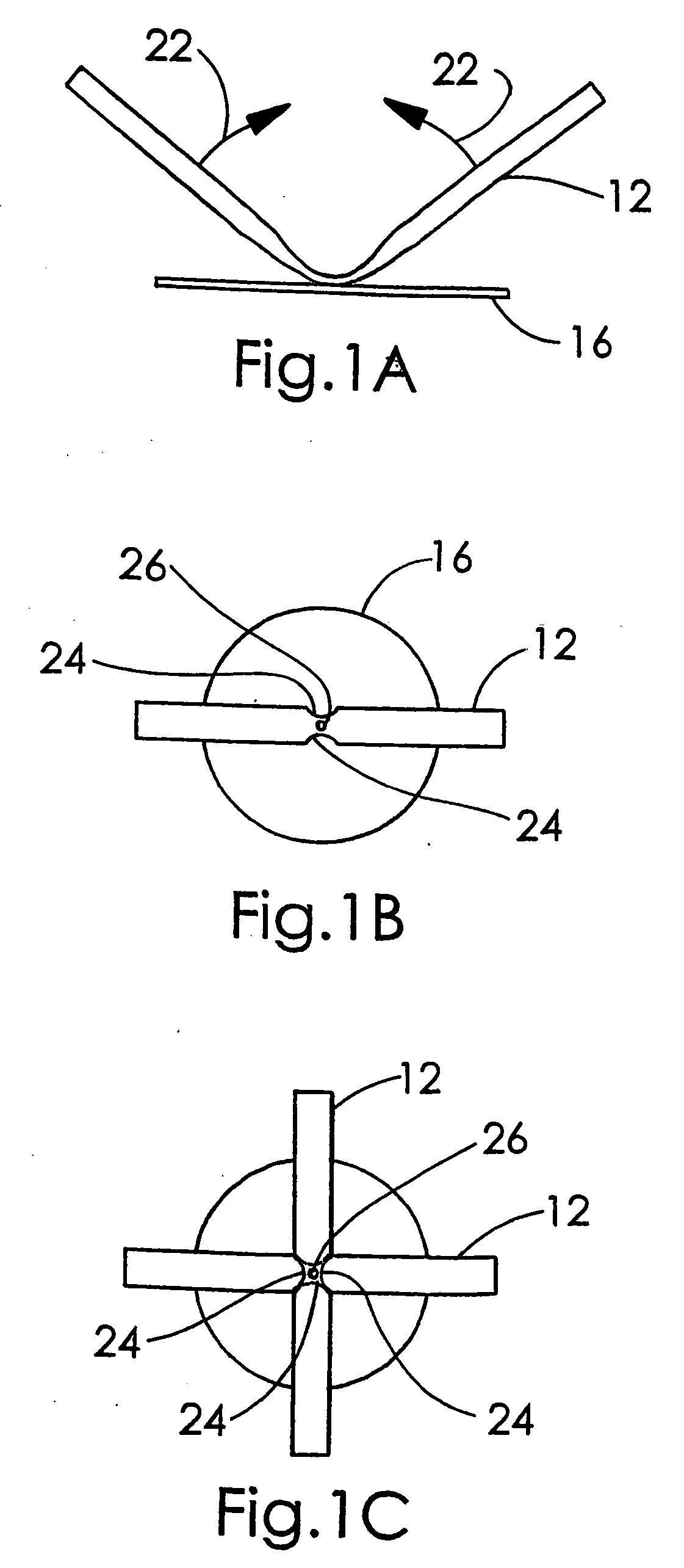
[0057] A first component used for making this device was a tube formed from the self-cohering web sheets that had an area density of approximately 8-10 mg / cm2 and a thickness of approximately 0.3 mm. The first step in making a tube was to cut an approximately 25 mm wide strip of the self-cohering web material from a piece of “unset” web sheet perpendicular to the belt direction used in forming the web. This strip of “unset” web material was then wrapped lengthwise around an approximately 5 mm diameter stainless steel rod into a “cigarette roll” having an e...

example 2

[0062] This example describes the construction of a corrugated tube hernia repair device of the present invention as shown in FIG. 4. A triblock copolymer of 50% PGA:TMC (w / w) was made and formed into a self-cohering web as generally taught by Hayes in U.S. Pat. No. 6,165,217. Sheets of this copolymer web material were formed into some of the components used in the construction of this device. Other components were made from expanded polytetrafluoroethylene (ePTFE) and from a bioabsorbable polymer adhesive, as described below.

[0063] A corrugated sheet was made by first placing a piece of the “unset” PGA:TMC web sheet (approximately 100 mm square, about 0.2 mm thick having and having an area density of approximately 4-6 gm / cm2) onto a piece of PeCap® polyester screen, product number 7-1000 / 45 (Sefar America, Monterey Park Calif.) material. This screen material, by virtue of its surface texture, was used to restrain the web material from dimensional change during the “setting” proces...

example 3

[0068] This example describes a method used to alter the stiffness and rate of bioabsorption of a bioabsorbable device. A solution was made by mixing 65% d,l-PLA:35% PGA available from Birmingham Polymers (Birmingham Ala.) in a 1:10 ratio by weight with acetone. A device as described in Example 1 was dipped into this solution which imbibed into the structure of the device, and then allowed to air dry. The resulting coated device was stiffer than prior to imbibing. Alternatively, this solution could be sprayed onto devices to achieve similar effects. Other copolymer ratios can also be used to vary the stiffness and rate of bioabsorption. Also, other ratios of polymer:acetone can be used to vary the final amount of polymer imbibed into or sprayed onto the structure of the device.


PUM


Abstract

An inguinal hernia repair device in the form of an implantable plug that is affixed at one end to the center region of a sheet of implantable material. The plug takes the form of a plurality of hollow members, arranged so as to be in substantially parallel relationship when implanted into a defect. The hollow members are preferably tubular members and are preferably bundled together by various means, such as bonding or wrapping a band or strand about the plurality of hollow members to maintain them in adjacent and contacting relationship during insertion into a defect. The device is provided with a base member for anchorage made of a composite material having a non-bioabsorable component and a bioabsorbable component.

Description

CROSS REFERENCE TO RELATED APPLICATIONS [0001] This application is a continuation-in-part of co-pending application Ser. No. 10 / 465,110, filed Jun. 18, 2003.FIELD OF THE INVENTION [0002] The present invention relates to the field of soft tissue defect repair devices, and more particularly to the field of inguinal hernia repair devices. BACKGROUND OF THE INVENTION [0003] The repair of inguinal hernias is one of the most commonly performed surgical procedures. Various prosthetic materials, typically porous to allow for tissue ingrowth, have been provided in a variety of combinations, forms and shapes. Surgical mesh, typically of polypropylene, has been commonly used, in some instances having been rolled up into a cylindrical shape and inserted into the defect as a plug. To reduce the tendency to migrate, these plugs are sometimes affixed at one end to the center of a sheet of material. The sheet is used to overlap the defect and for attachment to the adjacent tissue to reduce the like...

Claims


Application Information

Patent Timeline
IPC IPC(8): A61B17/00A61F2/00
CPCA61B17/0057A61F2/0063A61B2017/00615A61B2017/00597
Inventor CRAWLEY, JERALD M.HERMAN, JOHN M.MONTGOMERY, WILLIAM D.WHITE, CHARLES F.
Owner WL GORE & ASSOC INC
Why Eureka
Try Eureka