Method and system for transmitting data via switchable data networks

a data network and switchable technology, applied in data switching networks, hybrid switching fabrics, synchronisation arrangements, etc., can solve problems such as the inability to exclude collisions in the coupling units of switchable high-speed networks

Inactive Publication Date: 2005-08-04
SIEMENS AG
View PDF4 Cites 15 Cited by
  • Summary
  • Abstract
  • Description
  • Claims
  • Application Information

AI Technical Summary

Benefits of technology

[0022] Another particular advantage of the invention is that it enables a consistent exchange of real-time data in a deterministic communication system of different partial networks, each having different transmission rates and/or communication cycles. For the consistent transmission of real-time data it is decisive that the data are assigned to a specific transmission cycle, including beyond the communication interface between the individual partial networks. The invention enables such a fixed assignment of real-time data to specific transmission cycles beyond the boundaries of the partial networks.
[0023] In another exemplary embodiment of the invention, the consistent data exchange takes place via an intermediate buffer. This means that the receive port always writes the data to the common intermediate buffer and the transmit port retrieves the data from the intermediate buffer at the corresponding transmit instant. In addition, each port can have a transmit and a receive buffer. In this case, the depth of the transmit and receive buffers must be at least sufficient to accommodate a data packet of a maximum packet length. Only when the data packet has been fully received at the receive port are the data copied into the common intermediate memory. For transmission, the data are copied from the intermediate memory to the transmit buffer of the transmit port.
[0024] According to yet another exemplary embodiment of the invention, an access controller of the common intermediate memory ensures that no overtaking can occur during reading from and writing to the intermediate memory.
[0025] It is particularly advantageous that only one standard communication interface needs to be implemented at a coupling node and that no additional entity is necessary to recopy the data between the different co...

Problems solved by technology

It is therefore not possible to exclude collisions in the coupling units of...

Method used


Image

  • Method and system for transmitting data via switchable data networks
  • Method and system for transmitting data via switchable data networks
  • Method and system for transmitting data via switchable data networks

Examples


Embodiment Construction

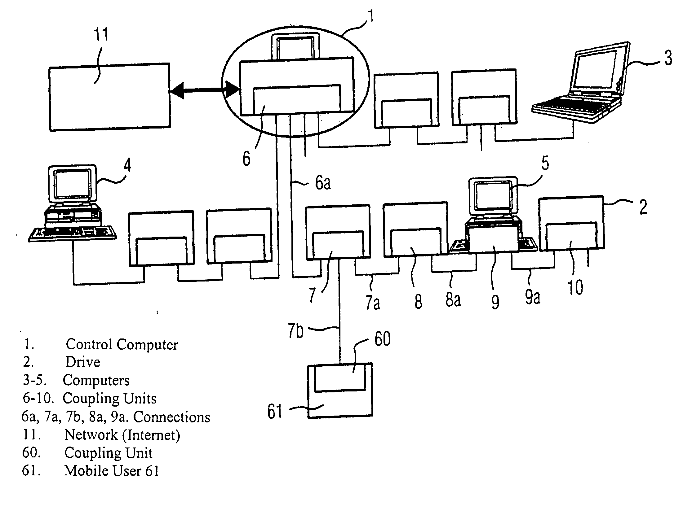
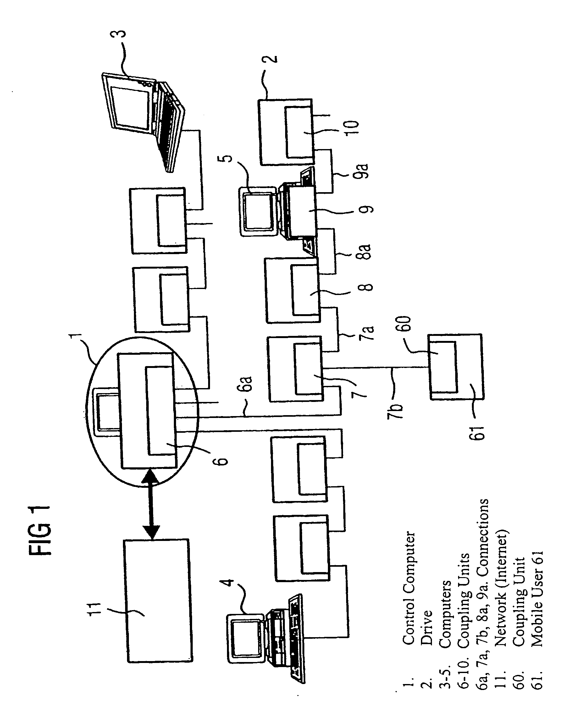
[0048]FIG. 1 is a schematic representation of an exemplary embodiment of a distributed automation system. For reasons of clarity and as part of the invention, each coupling unit is in this embodiment is already integrated in the respective user. In the related art, by contrast, each of the coupling units, which is already integrated in the respective local user here, is a stand-alone device that is inserted between two users. The integration of the respective coupling unit in a user is more cost-effective and easier to maintain.

[0049] The depicted automation system has a plurality of users that can simultaneously be transmitters and receivers, e.g., a control computer 1, a plurality of drives (only drive 2 is identified), a mobile user 61 and additional computers 3, 4, 5, which are interconnected into a switchable data network, particularly Ethernet, by connecting cables, particularly Ethernet cables, or by radio links. For reasons of clarity, only the connections 6a, 7a, 7b, 8a, 9...


PUM


Abstract

A method and a system for transmitting data over a switchable network, especially Ethernet, in the field of industrial installations, in which real-time critical data and non real-time critical data is transmitted. The switchable data network has at least one wireless transmission link between at least two users, especially a transmitter and a receiver. When a communication interface is created by way of a coupling unit of the data network between cyclically clocked communication connections differing in performance, the data is forwarded according to a “store and forward” method. The method and system enable a parallel transmission of real-time critical and non real-time critical data.

Description

[0001] This is a Continuation of International Application PCT / DE03 / 01467, with an international filing date of May 7, 2003, which was published under PCT Article 21(2) in German, and the disclosure of which is incorporated into this application by reference. FIELD OF AND BACKGROUND OF THE INVENTION [0002] The invention relates to a method and a system for transmitting data over switchable data networks, particularly Ethernet in the field of industrial installations, in which real-time critical and non real-time critical data are transmitted. The switchable data network has at least one wireless transmission link between at least two users, particularly a transmitter and a receiver. [0003] Data networks enable communication between a plurality of users through networking, i.e., the connection of individual users among each other. Communication is the transmission of data between the users. The data to be transmitted are sent as data messages, i.e., the data are combined into a plura...

Claims


Application Information

Patent Timeline
IPC IPC(8): H04L12/28H04L12/40H04L12/56H04L12/64H04L12/66
CPCH04L12/40117H04L12/6402H04W56/00H04L2012/6408H04L2012/6462H04L12/66
Inventor KASPER, MICHAELKRAUSE, KARL-HEINZSINN, ULRICH
Owner SIEMENS AG
Why Eureka
Try Eureka