[0011] As is well known to those skilled in the art, conventional microphone arrays typically include an arrangement of one or more microphones in some predetermined
layout. In general, each microphone in these arrays typically includes an associated preamplifier for providing amplification or
gain for analog audio signals captured by each microphone. Further, each of the input channels (i.e., each microphone / preamplifier combination) of such microphone arrays are typically matched so that that the sensitivity and frequency responses of those input channels are as close as possible to one another for any particular audio input. However, providing for matched components in a microphone array tends to increase both cost and test time when manufacturing such arrays.
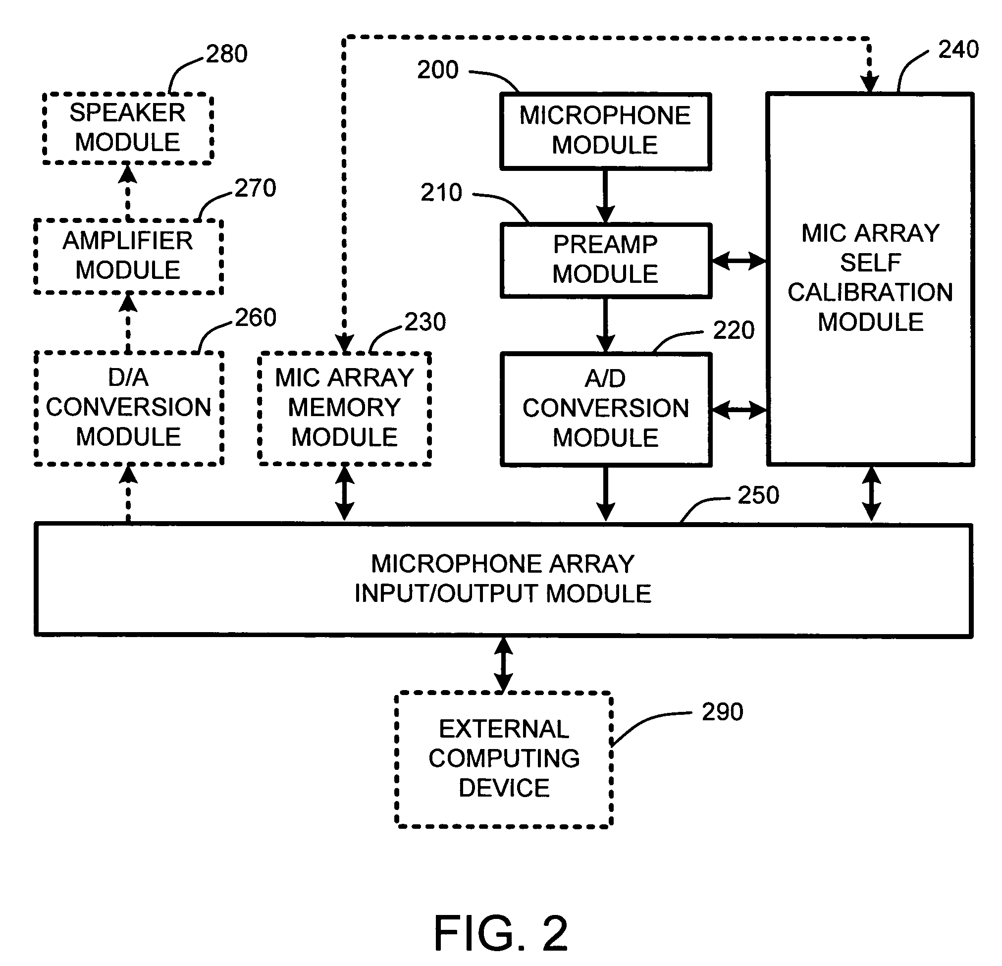
[0012] Therefore, in contrast to conventional microphone arrays, an analog preamplifier measurement system for a microphone array, as described herein, operates to solve the problems identified above by providing a modified microphone array with an integral “self-calibration system.” In general, this integral self-calibration system automatically determines frequency-domain responses of each preamplifier in the microphone array, and computes frequency-domain compensation gains, so that
digital signal processing applications can use those compensation gains for matching the output of each preamplifier. As a result, there is no need to predetermine exact operational characteristics of each channel of the microphone array, or to use expensive matched electronic components.
[0016] Once computed, these frequency-domain compensation gains can then be applied to the output of each corresponding preamplifier when processing actual audio inputs of the microphones associated with each preamplifier. This serves to make the output from each of the preamplifiers consistent, given the same or similar input to any of the microphones in the array. Consequently, using these computed frequency-domain compensation gains, audio processing software such as, for example, software for performing sound
source localization, beam forming, acoustic echo cancellation,
noise suppression, etc., can easily compensate for
phase response mismatches across all preamplifiers. Without this compensation, any
phase response mismatches would reduce the performance of the audio processing software.
[0017] Therefore, as a result of computing and providing these frequency-domain compensation gains for each preamplifier, there is no need to use expensive matched electrical components. Consequently, one
advantage offered by the integral self-calibration system described herein is that microphone arrays using this integral self-calibration system may be inexpensively produced by using relatively inexpensive non-matched electrical components including, for example, transistors, capacitors, resistors, op amps, etc.
[0020] As noted above, in one embodiment, the integral self-calibration system is included in a self-descriptive microphone array which makes use of external computing power for performing computations. In this embodiment, the frequency analysis for computing the frequency-domain compensation gains for each preamplifier is performed by an external computing device, such as a PC-type computer, or other computing device, coupled to the microphone array. One
advantage of this embodiment is that because the microphone array makes use of external processing power, there is no need to include relatively expensive onboard
signal processing software or hardware capabilities within the array itself. Consequently, the self-descriptive microphone array is relatively inexpensive to manufacture in comparison to conventional microphone array devices that include onboard audio processing capabilities. Note that the connection (a “microphone array interface”) between the self-descriptive microphone array and the external computing device is accomplished using any of a variety of conventional wired or
wireless computer interfaces, including, for example, serial, parallel, IEEE 1394,
USB, IEEE 802.11,
Bluetooth™, etc.
[0024] In another embodiment, in addition to including one or more microphones, the microphone array also includes one or more loudspeakers for reproducing one or more audio signals. For example, many microphone arrays, such as those arrays used for audio conferencing, frequently include both microphones and speakers. The microphones capture sound, and the speakers play back sound. Generally, conventional audio conferencing-type microphone arrays also include relatively expensive onboard acoustic echo cancellation capabilities so that local audio signals are not endlessly echoed during an audio conference.

