
Carburized and quenched member and method for production thereof

Inactive Publication Date: 2005-08-11
AISIN AW CO LTD
View PDF1 Cites 13 Cited by
  • Summary
  • Abstract
  • Description
  • Claims
  • Application Information

AI Technical Summary

Benefits of technology

[0012] In the present invention, a specific alloy of which the C content and the Si content and the hardenability J are within the specific ranges is used as a raw material. After a carburized layer is formed by performing the carburizing process in the oxidation inhibitive atmosphere, the quenching process is performed so as to fulfill the aforementioned conditions of monotonous cooling and the aforementioned condition of specific severity of quenching H. That is, only after the material characteristics and the production conditions are fulfilled, it becomes possible to provide a carburized and hardened member in which the strength is enhanced while the hardening strain is sufficiently reduced.
[0013] This will be further explained. The setting of the C content within the range of 0.1 to 0.50 wt. % makes it possible to secure an appropriate toughness and an appropriate strength of a non-carburized portion (internal portion) after the carburizing and quenching process. If the C content is less than 0.1 wt. %, the aforementioned effect is not sufficient. If the C content exceeds 0.50 wt. %, the pre-quenching hardness becomes excessively high, thus creating a possibility of increased processing cost and reduced toughness. Furthermore, due to increased structural transformation rate of the interior of the non-carburized portion following the carburizing and quenching process, transformation stress increases, and due to great quenching strain, the component part accuracy may degrade.
[0014] Furthermore, in the present invention, the member positively contains Si as a component, and the content thereof is 0.50 to 1.50 wt. %. The carburizing process is performed in an oxidation inhibitive atmosphere. Therefore, it becomes possible to achieve improved plane fatigue strength, improved hardenability, improved resistance to temper softening, etc, while reducing the intergranular oxidation, which is likely to occur at the time of the carburizing process.
[0017] The severity of quenching H is limited within the range of 0.01 to 0.08 (cm−1). If the alloy having the specific amount of carbon and having the hardenability is used, it becomes possible to substantially prevent or reduce the hardenability strain at the time of hardening process and therefore secure excellent dimensional accuracy.
[0020] As the monotonous cooling is adopted as an essential condition, precipitation of carbides can be substantially prevented or reduced.
[0021] With regard to the monotonous cooling condition, it is possible to select a cooling condition such that the cooling does not enter a region of a nose of an S curve indicated in an isothermal transformation diagram within the carburized portion. This selection secures sufficient martensite transformation.

Problems solved by technology

However, improved hardenability normally leads to increased hardening strain, as well known.
There is a possibility that the strength prior to the carburizing and quenching process may increase resulting in degraded processability and therefore increased cost of processing.

Method used


Image

  • Carburized and quenched member and method for production thereof
  • Carburized and quenched member and method for production thereof
  • Carburized and quenched member and method for production thereof

Examples


example 1

[0047] As Example 1, results of experiments conducted to verify advantages of the present invention will be described.

[0048] Steels (Steel 11 to Steel 14) having chemical compositions shown in Table 1, after being melt-formed in an arc furnace, were hot-rolled into round bars having a diameter of 150 mm and a diameter of 32 mm. The round bars were normalized by keeping them at 925° C. for an hour and then air-cooling them.

[0049] Steel 11 and Steel 12 are steel grades having new compositions developed in the example. Steel 13 and Steel 14 are steel grades corresponding to case hardening steels SCM420 and SNCM 815 according to JIS.

[0050] Firstly, for each steel grade, a hardenability J was determined by conducting a Jominy end quenching method according to JIS: G0561.

[0051] Results are shown in Table 1. This characteristic is a characteristic of a raw material irrelevant to the production method described below.

TABLE 1SteelComponent element (wt %)gradeCSiMnSNiCrMoBTiMbAlNHardena...

example 2

[0087] In this example, steels indicated in Table 6 (Steels 21 to 24 and Steels 31 to 38) were melted and formed into ingots, which were bloom-rolled and bar-rolled to produce round bars of 70 mm in diameter.

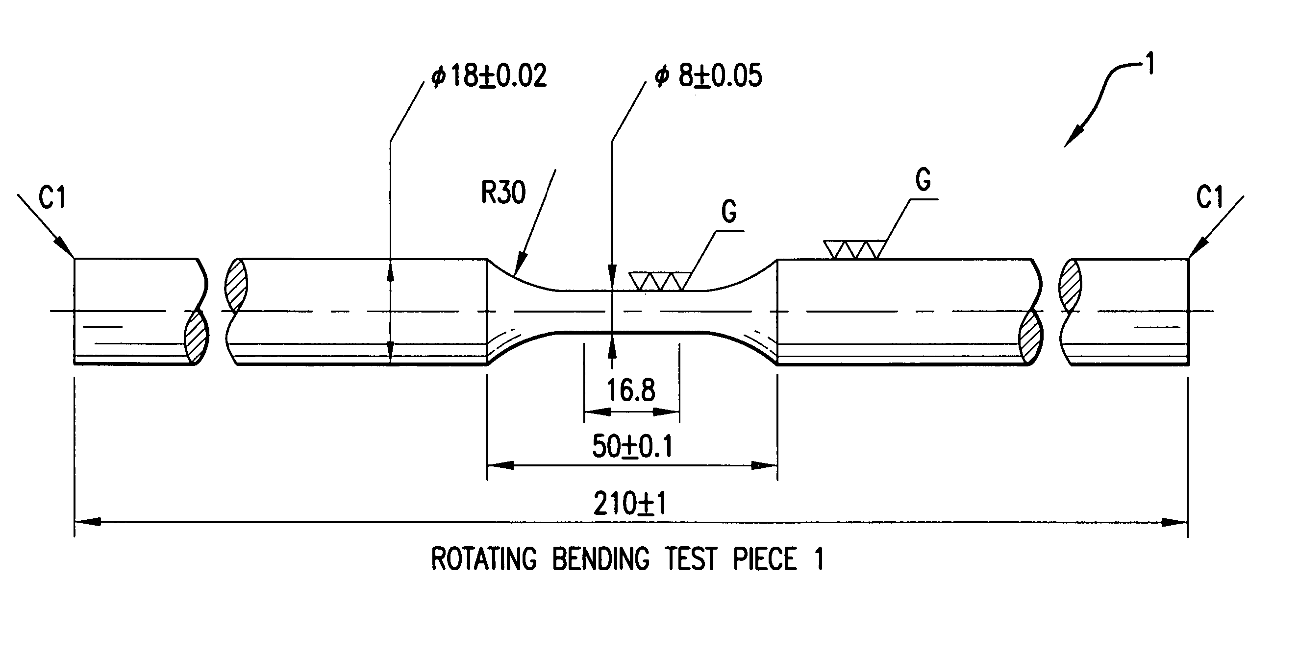
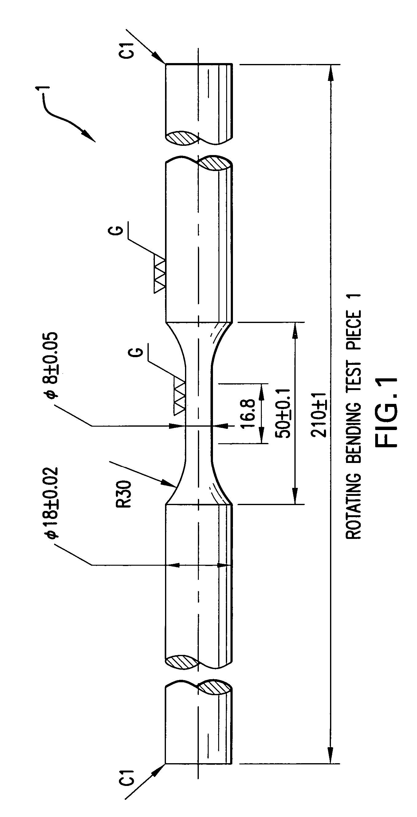
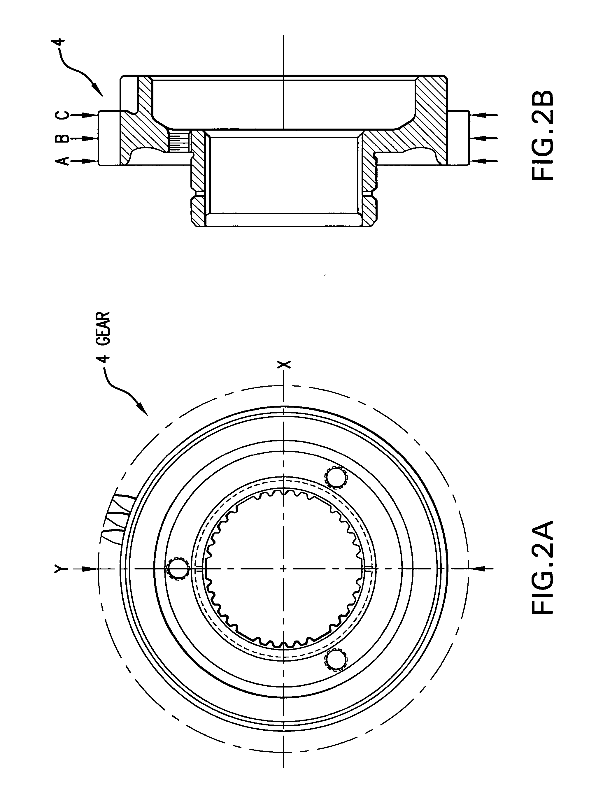
[0088] Subsequently, the round bars of 70 mmφ were stretched to 120 mmφ by hot forging. After being normalized at 925° C., the materials were formed into test pieces and toothed gears as in Example 1 (see FIGS. 1 and 2).

[0089] The test pieces and the gears were processed separately by three different production methods (Processes 3 to 5).

[0090]“Process 3” is characterized by gas carburization and oil quenching. In this process, steel is carburized and quenched and then tempered in a carburizing gas atmosphere in the manner of heating at 930° C. for 5 hours→diffusion at 850° C. for 1 hour→oil-quenching at 130° C.→tempering at 180° C. for 1 hour. The severity of quenching H in this case is 0.15 (cm−1).

[0091]“Process 4” is characterized by vacuum carburization and gas cooling. ...


PUM

PropertyMeasurementUnit
Temperatureaaaaaaaaaa
Lengthaaaaaaaaaa
Fractionaaaaaaaaaa

Abstract

A carburizing and hardening method enhances strength while sufficiently reducing hardening strain, without increasing the production cost, and a carburized and hardened member produced thereby. The raw material is an alloy steel which contains Fe as a main component, 0.10 to 0.50 wt. % C and 0.50 to 1.50 wt. % Si and having a hardenability J, based on an end quenching test, in a range of 35 to 50 (at 12.5 mm). After the raw material is formed into the desired shape, a carburized layer is formed by carburizing in an oxidation inhibiting atmosphere. After the carburizing, quenching is performed with cooling, uninterrupted by temperature rise, from a pearlite transformation point (A1 point) to a martensite transformation start point (Ms point), and with a severity of quenching H in a range of 0.01 to 0.08 (cm−1).

Description

TECHNICAL FIELD [0001] The present invention relates to a carburized and hardened member that is excellent in fatigue strength and dimensional accuracy, and a production method for the member. BACKGROUND ART [0002] For example, for power transmission component parts of an automatic transmission, for example, gears and the like, carburized and hardened members subjected to a carburizing and quenching process are often used in order to increase the surface hardness and the toughness. [0003] Conventional carburized and hardened members are normally produced by forming a case hardening steel (JIS: SCM420H, SCR420H, SNCM220) or the like into a desired shape, and then gas-carburizing the steel in a carburizing atmosphere, and then quenching it in an oil or the like. [0004] As for the carburized and hardened members, cost cut and performance improvement are demanded more strongly than ever. [0005] In order to achieve both a cost cut and a performance improvement, it is necessary to remove ...

Claims


Application Information

Patent Timeline
IPC IPC(8): C23C8/22C23C8/80
CPCC23C8/80C23C8/22
Inventor TANIGUCHI, TAKAOTSUKAMOTO, KAZUMASAOHBAYASHI, KOUJIHANYUDA, TOMOKIKUREBAYASHI, YUTAKAKANISAWA, HIDEOITOH, SEIJI
Owner AISIN AW CO LTD
Learn More