UWB signal generator using optical FSK modulator

a technology of optical fsk modulator and signal generator, applied in multiplex communication, optics, instruments, etc., can solve the problems of disadvantageous center frequency or band limit, signal generator must use pulse light, and cannot transmit electric pulses simultaneously with another signal

Inactive Publication Date: 2005-08-11
NAT INST OF INFORMATION & COMM TECH
View PDF5 Cites 32 Cited by
  • Summary
  • Abstract
  • Description
  • Claims
  • Application Information

AI Technical Summary

Benefits of technology

[0008] It is another object of the present invention to provide a UWB signal generator using an optical FSK modulator which can be used in optical information communication or the like and which can transmit information at a high speed.
[0030] According to the present invention, a signal generator which can simultaneously generate an intensity modulating signal and a UWB signal without using WDM can be provided. More specifically, according to the present invention, at least one of the above advantages can be achieved.

Problems solved by technology

However, in this signal generator, since only an electric pulse matched with the characteristics of the antenna is output, the electric pulse cannot be transmitted simultaneously with another signal.
Another disadvantage is that the signal generator must use pulse light.
In the signal generator, since the output pulse mainly depends the characteristics of the antenna, a center frequency or a band is disadvantageously limited.
In the signal generator, many pieces of light having frequencies which are not actually transmitted are wastefully generated.
In the signal generator, a stability control mechanism is disadvantageously complex and expensive.

Method used


Image

  • UWB signal generator using optical FSK modulator
  • UWB signal generator using optical FSK modulator
  • UWB signal generator using optical FSK modulator

Examples


Embodiment Construction

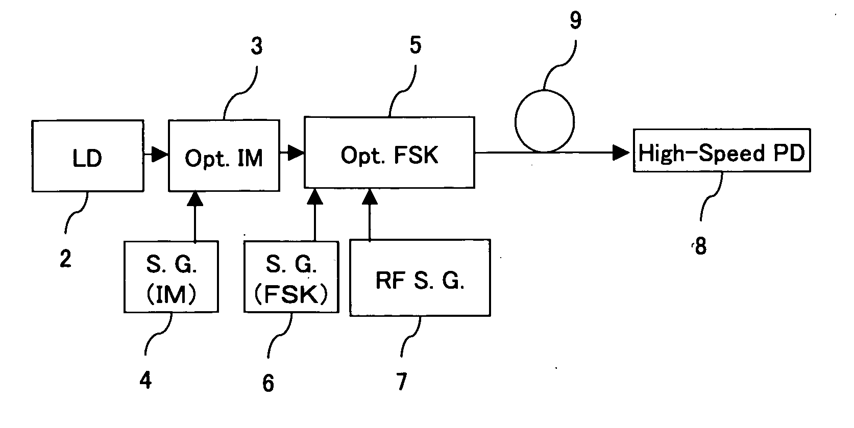
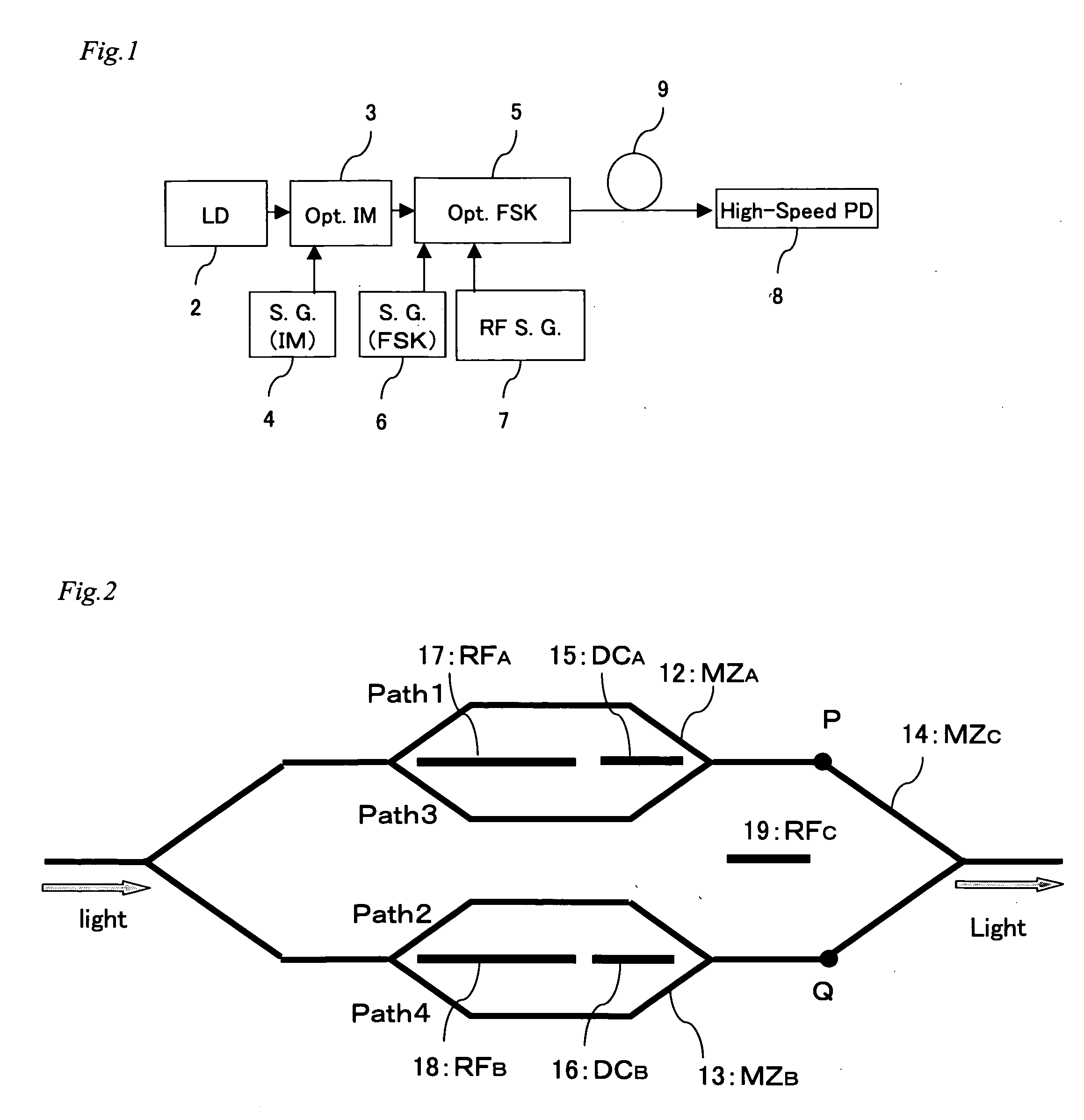
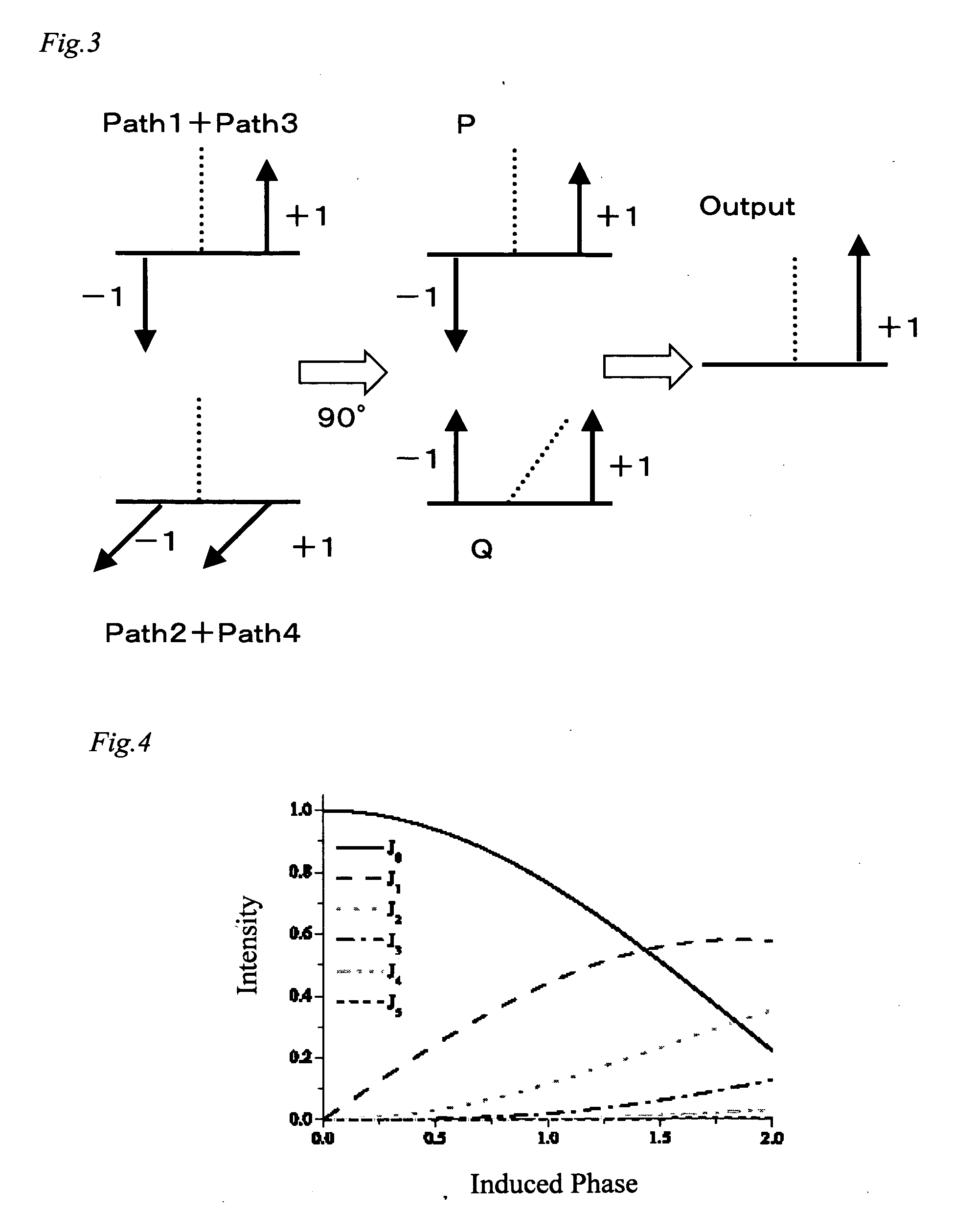
[0041] In an optical FSK modulator, an upper side band and a lower side band which are transiently, simultaneously generated in a switching operation interfere with each other to generate a component having a frequency which is twice an RF signal frequency (fFSK) of the optical FSK modulator. When output light from a modulator is guided to a photodetector (high-speed photodetector) which can respond to a frequency component having a frequency which is a frequency difference or more of the two components (which is twice or more RF signal frequencies input to an RFA electrode and an RFB electrode), an RF signal having a frequency corresponding to the frequency difference is generated only while the two components are simultaneously generated. Since this phenomenon is a transitive phenomenon occurring in a frequency switching state, when a signal (RFC) for switching optical frequencies is assumed as a rectangular pulse having short rise / fall time, an RF signal can be generated. The UWB...


PUM

PropertyMeasurementUnit
repetition frequencyaaaaaaaaaa
center frequencyaaaaaaaaaa

Abstract

A UWB signal generator includes: a laser light source for generating laser light, an optical intensity modulator for modulating an intensity of laser light from the laser light source, a signal source of the optical intensity modulator for outputting a signal transmitted to the optical intensity modulator, an optical frequency shift keying (optical FSK) modulator to which output light from the optical intensity modulator is input, a signal source for controlling a signal transmitted to an RFC electrode of the optical FSK modulator, a high-frequency electric signal source for controlling a signal transmitted to an RFA electrode and an RFB electrode of the optical FSK modulator, and a high-speed photodetector for detecting an output from the optical FSK modulator.

Description

FIELD OF INVENTION [0001] The present invention relates to a UWB signal generator and the like using an optical FSK modulator. BACKGROUND OF THE INVENTION [0002] In recent years, a UWB technique has attracted attention in an effort to further increase in speed of short-distance wireless communication in a wireless LAN or the like. The UWB is an abbreviation of a Ultra-Wide Band. The UWB technique is a wireless communication technique using a short-pulse RF signal. The UWB technique is characterized in that a frequency band occupied by a signal is ultra wide. At the present, a frequency is allocated in a microwave band under FCC in the USA, and the UWB technique is developed in an effort to realize the UWB technique around a several-gigahertz band. On the other hand, in research institutes, a millimetric-wave band UWB technique also begins to be examined to realize a gigabit-class wireless LAN. As methods of generating UWB signals, an IR (Impulse Radio) and a DS-SS (Direct Sequence S...

Claims


Application Information

Patent Timeline
Patent Type & Authority Applications(United States)
IPC IPC(8): H04B1/7163G02F1/05H04B10/516H04B10/548H04B10/61H04J13/00H04L25/49
CPCH04B1/7174
Inventor KAWANISHI, TETSUYAIZUTSU, MASAYUKI
Owner NAT INST OF INFORMATION & COMM TECH
Why Eureka
Try Eureka