
Methods of forming metal interconnections of semiconductor devices by treating a barrier metal layer

a metal layer and barrier layer technology, applied in the field of metal interconnection forming methods of semiconductor devices, can solve the problems of increasing the difficulty of metal interconnection, physical vapor deposition (pvd) such as a sputtering process may not be amenable to use during the deposition process, etc., to reduce the nucleation of the metal layer on the anti-nucleation layer, reduce or prevent abnormal growth of metallic materials

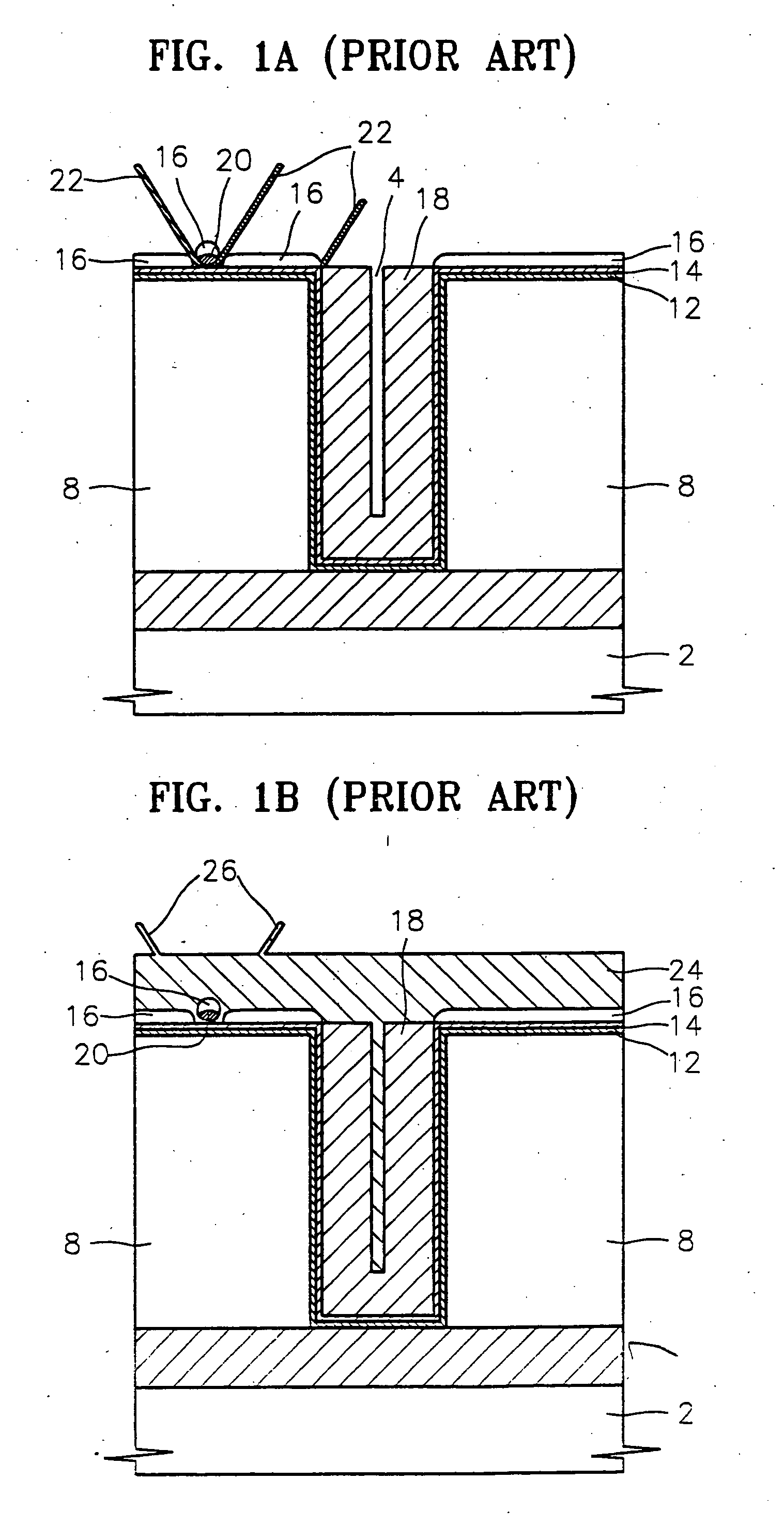
Active Publication Date: 2005-08-18
SAMSUNG ELECTRONICS CO LTD
View PDF43 Cites 52 Cited by
  • Summary
  • Abstract
  • Description
  • Claims
  • Application Information

AI Technical Summary

Benefits of technology

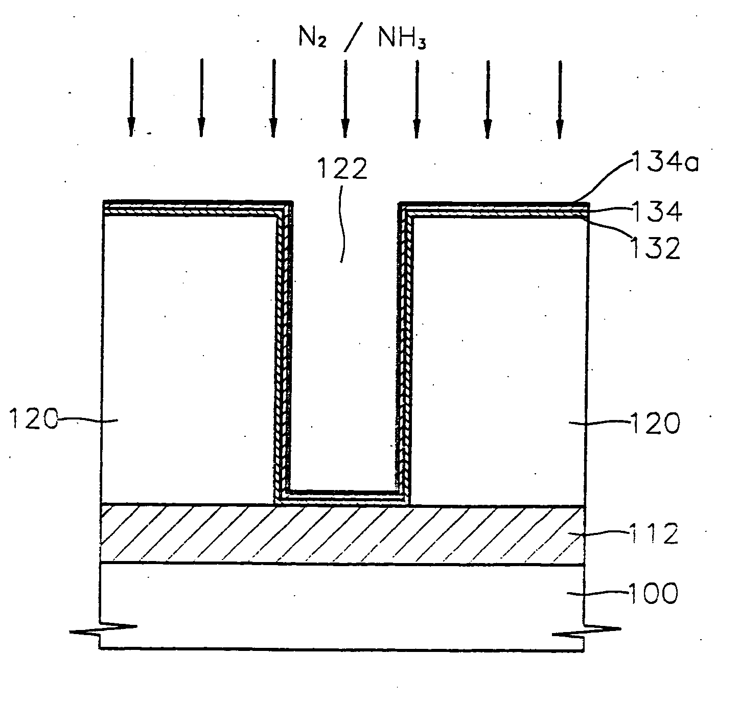
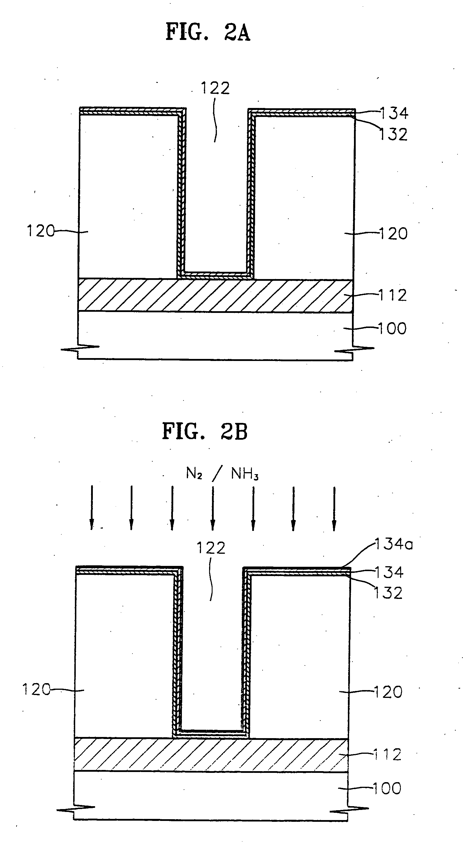
[0019] In other embodiments of the present invention, a metal interconnection of a semiconductor device is fabricated by forming a dielectric layer pattern including a contact hole therein, on a substrate. A barrier metal layer is formed in the contact hole and on the dielectric layer pattern outside the contact hole. An anti-nucleation layer is formed on the barrier metal layer outside the contact hole, and a metal layer is formed in the contact hole. However, after forming the barrier metal layer, the surface of the barrier metal layer is thermally treated so as to reduce selective metal layer growth at a circumference of the contact hole, and / or on the dielectric pattern, compared to absence of the thermal treatment.
[0022] According to embodiments of the present invention, while fabricating a metal interconnection of a semiconductor device using preferential metal deposition (PMD), a barrier metal layer is formed and then thermally treated in a nitrogen-containing atmosphere to oxidize the surface of the barrier metal layer before forming an anti-nucleation layer. Nucleation of the metal layer on the anti-nucleation layer may be reduced compared to absence of the oxide of the barrier layer. Accordingly, even if a portion of the barrier metal layer, which is incompletely covered with the anti-nucleation layer, is exposed around particles and / or the circumference of a contact hole, it is possible to reduce or prevent a metallic material from abnormally growing on the exposed portion of the barrier metal layer when a metal layer is formed in the contact hole using selective chemical vapor deposition (CVD).

Problems solved by technology

As the critical dimensions of integrated circuits become smaller and smaller, it may become increasingly difficult to make a metal interconnection, e.g., an aluminum interconnection, for use in a semiconductor device.
Thus, physical vapor deposition (PVD) such as a sputtering process may not be amenable for use during the deposition process.

Method used


Image

  • Methods of forming metal interconnections of semiconductor devices by treating a barrier metal layer
  • Methods of forming metal interconnections of semiconductor devices by treating a barrier metal layer
  • Methods of forming metal interconnections of semiconductor devices by treating a barrier metal layer

Examples


Embodiment Construction

[0025] The present invention now will be described more fully hereinafter with reference to the accompanying drawings, in which embodiments of the invention are shown. However, this invention should not be construed as limited to the embodiments set forth herein. Rather, these embodiments are provided so that this disclosure will be thorough and complete, and will fully convey the scope of the invention to those skilled in the art. In the drawings, the thickness of layers and regions are exaggerated for clarity. Like numbers refer to like elements throughout. It will be understood that when an element such as a layer, region or substrate is referred to as being “on” or extending “onto” another element, it can be directly on or extend directly onto the other element or intervening elements may also be present. In contrast, when an element is referred to as being “directly on” or extending “directly onto” another element, there are no intervening elements present.

[0026] It also will ...


PUM

PropertyMeasurementUnit
temperatureaaaaaaaaaa
pressureaaaaaaaaaa
pressureaaaaaaaaaa

Abstract

A metal interconnection of a semiconductor device is fabricated by forming a dielectric pattern including a hole therein on a substrate, and forming a barrier metal layer in the hole and on the dielectric layer pattern outside the hole. At least some of the barrier metal layer is oxidized. An anti-nucleation layer is selectively formed on the oxidized barrier metal layer outside the hole that exposes the oxidized barrier metal layer in the hole. A metal layer then is selectively formed on the exposed oxidized barrier layer in the hole.

Description

RELATED APPLICATION [0001] This application claims the benefit of Korean Patent Application No. 2002-0030294, filed May 30, 2002, the disclosure of which is hereby incorporated herein by reference in its entirety, as if set forth fully herein. FIELD OF THE INVENTION [0002] This invention relates to methods of fabricating semiconductor devices such as integrated circuit devices and semiconductor devices so fabricated, and more particularly to methods of forming metal interconnections for semiconductor devices and metal interconnections-so fabricated. BACKGROUND OF THE INVENTION [0003] As the critical dimensions of integrated circuits become smaller and smaller, it may become increasingly difficult to make a metal interconnection, e.g., an aluminum interconnection, for use in a semiconductor device. In forming a metal interconnection, it may be desirable to completely fill a contact hole, which is a connection between a lower conductive layer and an upper aluminum interconnection, or ...

Claims


Application Information

Patent Timeline
Patent Type & Authority Applications(United States)
IPC IPC(8): H01L21/28H01L21/285H01L21/768
CPCH01L21/28556H01L21/76843H01L21/76846H01L2221/1089H01L21/76876H01L21/76879H01L21/76882H01L21/76856A61M21/02A61M2021/0027A61N1/0452A61N1/20A61N1/328A61N1/3603
Inventor YUN, JU-YOUNGCHOI, GIL-HEYUNKIM, BYUNG-HEELEE, JONG-MYEONGYANG, SEUNG-GILSEO, JUNG-HUN
Owner SAMSUNG ELECTRONICS CO LTD
Learn More