Ultrasonic scaler tip incorporating a depth gauge

a technology of ultrasonic scaler and depth gauge, which is applied in the direction of cleaning process and apparatus, medical science, cleaning using liquids, etc., can solve the problem that the scaler tip cannot be used as a probe during normal ultrasonic operation, and the depth scale type of the scaler tip cannot be applied in the direction of medical science, etc., to achieve accurate judgment of the tip position

Inactive Publication Date: 2005-08-18
MILNE STEPHANIE C
View PDF9 Cites 21 Cited by
  • Summary
  • Abstract
  • Description
  • Claims
  • Application Information

AI Technical Summary

Benefits of technology

[0014] The present invention provides an ultrasonic scaler tip with depth gauge or scale having an appearance similar to those found on dental probe tips. The addition of a dental probe-type depth scale to a dental scaler tip does not permit the scaler tip to be used as a probe during normal ultrasonic operation. However, it allows the operator to more accurately judge the position of the tip with respect to the location of tissue alveolar bone. A typical cleaning operation would involve a two step process, with the depth of pockets and / or root canals being measured with a dental probe tip and noted. Subsequent use of an ultrasonic scaler tip would take into account the depth measurements previously noted so as to avoid damage to the unseen tissue and alveolar bone. Whereas the banded depth gauge on a dental probe tip need not be particularly durable, the tip of an ultrasonic scaler tip must be able to withstand some 18,000 to 50,000 strokes per second against calcified deposits.
[0015] The banded scaler tip of the present invention may be fabricated in various ways. For a first embodiment of the invention, the stainless steel tip is machined so that the surfaces where the dark-colored cylindrical bands will be are recessed. A wear resistant material is then deposited over the surface of the entire tip to a depth that is at least the depth of the recessed, thereby filling the recessed surface areas. The wear-resistant material may be selected from the group which includes boron carbide (black), black amorphous diamond-like carbon, titanium nitride (gold), titanium aluminum nitride (brown), zirconium nitride (gold), tungsten carbide (grey) and silicon carbide (black). The wear-resistant material may be applied to the tip using physical vapor deposition, chemical vapor deposition or plasma spraying or other similar process that provides a dark and preferably black coating. The tip is then machined until the stainless steel of the tip is exposed on the surfaces adjacent the recessed areas. Optionally, a smooth transparent wear-resistant material, such as diamond-like carbon or aluminum oxide, may then be deposited over the entire tip, covering both the light-colored stainless steel bands and the dark-colored bands. Because it is nearly as hard as diamond, the diamond-like carbon coating is preferred. The transparent wear-resistant material coating ensures that all surfaces of the tip are uniformly hard so that any wear will occur evenly and without creating steps, as would occur if the band regions of stainless steel were to wear at a faster rate than the band regions of the wear-resistant material. For an alternative and preferred second embodiment of the invention, very thin bands of a dark, wear-resistant material are deposited on the tip. This may be done using a masking process or simply by depositing the material over a major portion of the entire tip and then selectively polishing the tip to leave the bands. Once the bands are formed, a transparent wear-resistant material is applied over the entire tip.

Problems solved by technology

The addition of a dental probe-type depth scale to a dental scaler tip does not permit the scaler tip to be used as a probe during normal ultrasonic operation.

Method used


Image

  • Ultrasonic scaler tip incorporating a depth gauge
  • Ultrasonic scaler tip incorporating a depth gauge
  • Ultrasonic scaler tip incorporating a depth gauge

Examples


first embodiment

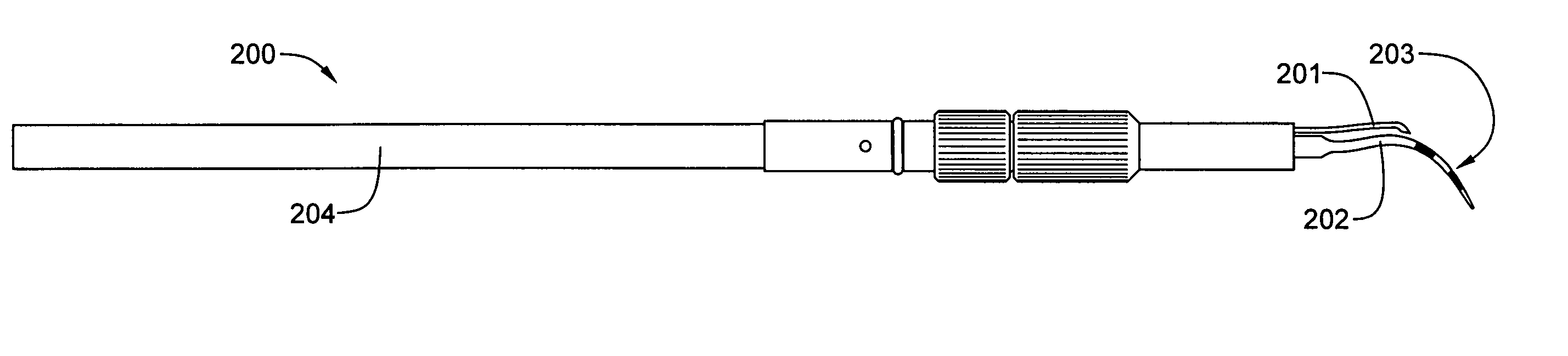
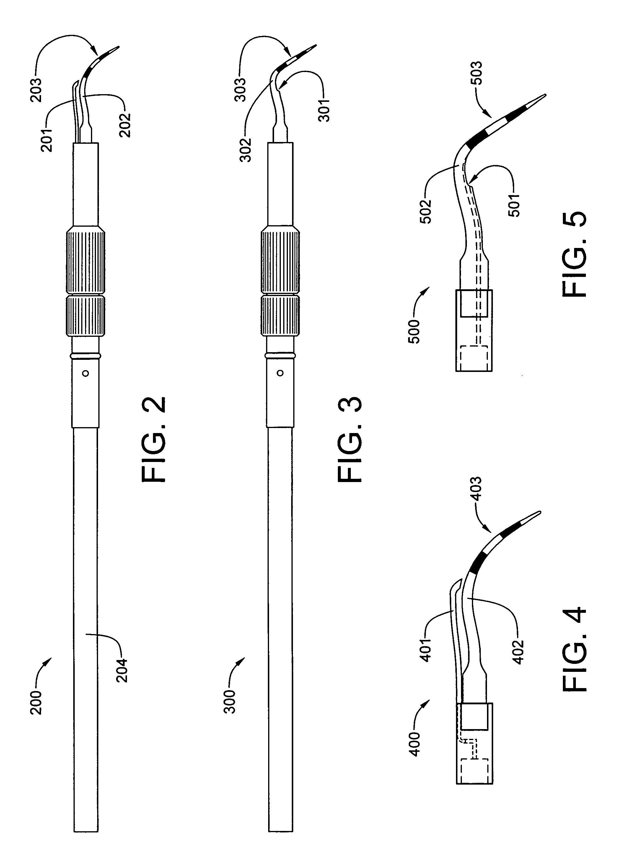
[0030] Referring now to FIG. 2, a first embodiment magnetostrictive scaler insert 200 having an external upper fluid tube 201, incorporates a curved scaler tip 202 having a multi-banded depth gauge 203 constructed in accordance with the present invention. As is typical of magnetostrictive scaler inserts, this one has an attached stack of laminations 204 which have been stamped from a magnetostrictive material. The stack 204 functions as a transducer by longitudinally expanding and contracting at an operational resonant frequency, when excited by the energizing coil in the handpiece.

second embodiment

[0031] Referring now to FIG. 3, a second embodiment magnetostrictive scaler 300 insert having a lower peripheral fluid orifice 301, incorporates an angled scaler tip 302 having a multi-banded depth gauge 303 constructed in accordance with the present invention.

[0032] Referring now to FIG. 4, a first embodiment scaler tool 400 for a piezoelectric scaler has an external upper fluid tube 401, and incorporates a curved scaler tip 402 having a multi-banded depth gauge 403 constructed in accordance with the present invention. The scaler tool 400 is desiged to attach directly to a piezoelectric transducer, which is incorporated in the handpiece.

[0033] Referring now to FIG. 5, a second embodiment scaler tool 500 for a piezoelectric scaler has a lower peripheral fluid orifice 501, and incorporates an angled scaler tip 502 that is equipped with a multi-banded depth gauge 503 constructed in accordance with the present invention.

[0034] The multi-banded depth gauge, that is the focus of the pr...


PUM


Abstract

An ultrasonic scaler tip incorporating a multi-banded depth gauge allows a dental professional to more accurately judge the position of the tip with respect to the location of live tissue and alveolar bone. A typical cleaning operation would involve a two step process, with the depths of pockets being measured with a dental probe tip, the depths noted, and subsequently referred to during a cleaning of the teeth. The depth gauge is fabricated of durable coatings so as to be able to withstand the harsh conditions to which it will be repeatedly subjected. The banded scaler tip of the present invention may be fabricated in various ways. For a preferred embodiment, very thin bands of a dark-colored cylindrical bands are created on the tip. The entire tip is then covered by a transparent wear-resistant coating.

Description

BACKGROUND OF THE INVENTION [0001] 1. Field of the Invention [0002] This invention relates generally to endodontic and periodontal ultrasonic dental scaler devices, and more specifically, to tips and inserts for those devices. [0003] 2. History of the Prior Art [0004] It is important to preventive dentistry and healthy teeth that teeth be kept clean. Over time, various deposits can form on teeth. These deposits can form on the surface of a tooth below the gum line or in the periodontal pocket. Such deposits can take the form of calculus on the surface of teeth. Calculus is a solid material that bonds to the surface of teeth over a period of time. In order to maintain healthy teeth and gums, it should be removed periodically. [0005] Many devices and methods have been developed over the years in attempts to better clean teeth. Early tools included manual picks and scrapers. However, within the last quarter century, a number of more sophisticated and effective tools have been developed...

Claims


Application Information

Patent Timeline
Patent Type & Authority Applications(United States)
IPC IPC(8): A61C3/03A61C17/20
CPCA61C17/20A61C3/03
Inventor MILNE, STEPHANIE C.
Owner MILNE STEPHANIE C
Why Eureka
Try Eureka