Ion implantation

a technology of ion beams and ion beams, which is applied in the field of ion beams, can solve the problems of inability to achieve the above-mentioned precautions, inability to fix the ion beam, so as to reduce the cooling effect, increase the energy, and increase the heating

Inactive Publication Date: 2005-08-18
APPLIED MATERIALS INC
View PDF5 Cites 55 Cited by
  • Summary
  • Abstract
  • Description
  • Claims
  • Application Information

AI Technical Summary

Benefits of technology

[0032] This method may be accompanied by the steps of maintaining or increasing the power supplied to the cathode. For example, the ion source may comprise an indirectly heated cathode and three power supplies: a filament supply (for the cathode's filament), a bias supply (for biasing within the indirectly heated cathode) and an arc supply (for biasing the anode relative to the cathode). Power supplied by the filament supply and the bias supply may be maintained, or may be increased to match the power of the arc supply prior to operating the first switch. This is to minimise any cooling in the ion source, and in the cathode in particular, when arc discharging ceases. Indirectly heated cathodes comprise a filament in front of an end cap. Increasing power supplied by the filament supply generates more electrons to be accelerated into the end cap, whilst increasing the power supplied by the bias supply increases the energy with which the electrons strike the end cap: in either case, the cathode enjoys greater heating from the electrons to compensate for the heating otherwise provided by the arcing.

Problems solved by technology

The precautions described above cannot be effected if the ion beam incident on the substrate is not itself uniform over time.
Unfortunately, instabilities of the ion beam are inevitable and result from discharges in the ion source area for example.
The effect of these instabilities is that there is a “glitch” in the ion beam in that the flux will usually drop significantly within a short period of time.
The drop in ion beam flux leads to areas of the semiconductor wafer receiving a lower level of doping that may lead to the production of faulty semiconductor devices.
Again, this produces incorrect dosing that may lead to faulty devices.
The above problem is particularly severe for serial processing ion implanters that use mechanically scanned substrate holders, as will now be explained.
Fast scan speeds require the ion beam to make many passes over the substrate to achieve a desired dosing: any instability in the beam during a single pass leads to a small residual dosing error due to dilution by the many subsequent passes.
The adverse effects are far more severe in serial processing where the slow scan speeds result in fewer passes to achieve the same dosing.

Method used


Image

  • Ion implantation
  • Ion implantation
  • Ion implantation

Examples


Embodiment Construction

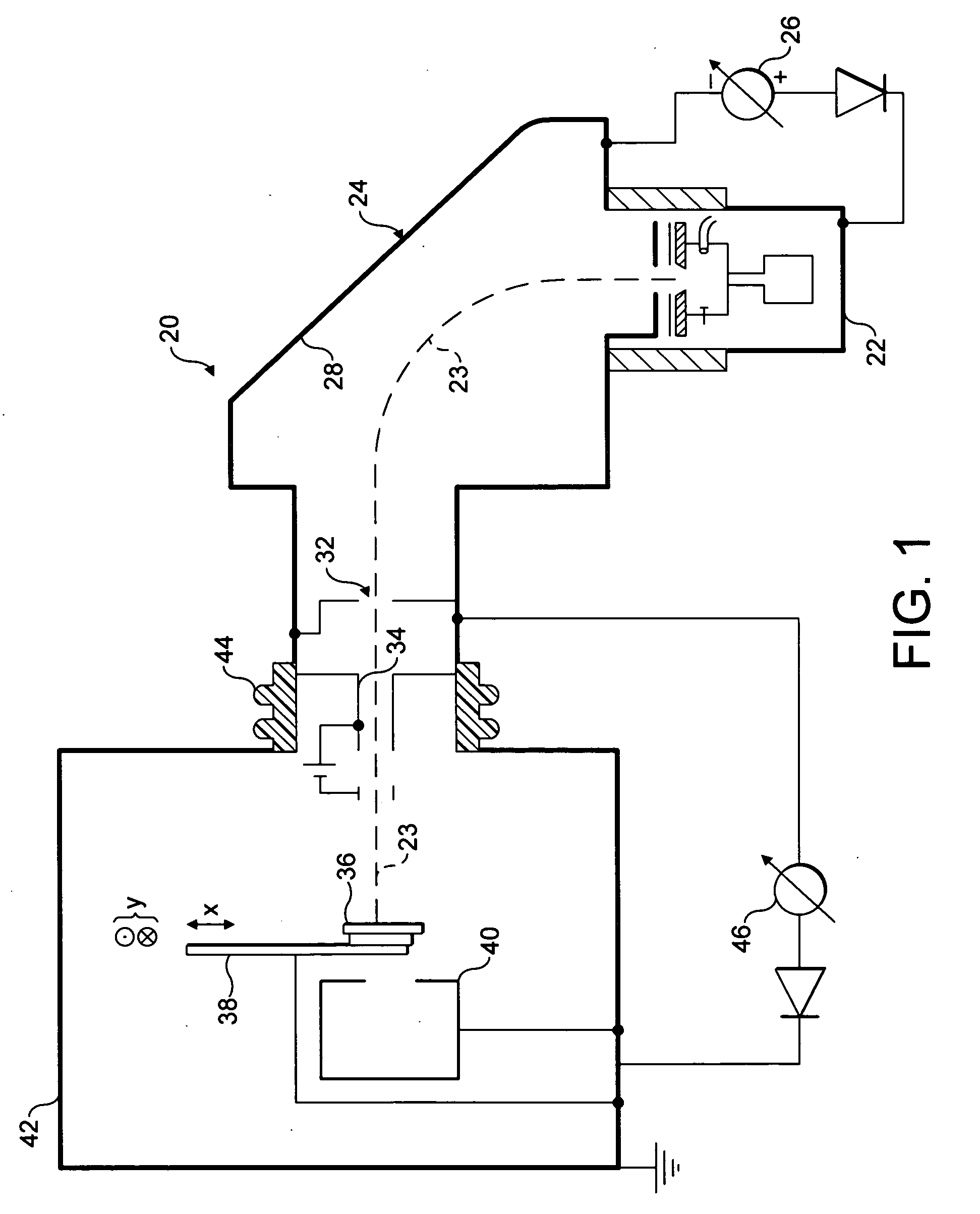
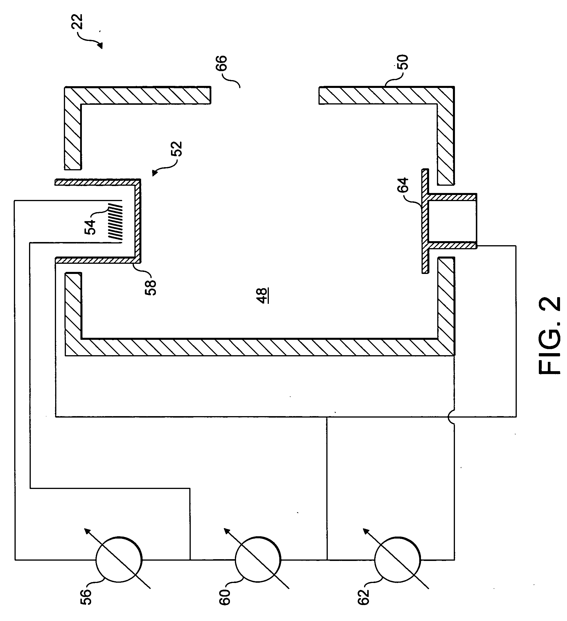
[0044]FIG. 1 shows a typical ion implanter 20 comprising an ion beam source 22 such as a Freeman or Bernas ion source that is supplied with a pre-cursor gas for producing an ion beam 23 to be implanted into a wafer. The ions generated in the ion source 22 are extracted by an extraction electrode assembly. The flight tube 24 is electrically isolated from the ion source 22 and a high-tension power supply 26 supplies a potential difference therebetween.

[0045] This potential difference causes positively charged ions to be extracted from the ion source 22 into the flight tube 24. The flight tube 24 includes a mass-analysis arrangement comprising a mass-analysing magnet 28 and a mass-resolving slit 32. Upon entering the mass-analysis apparatus within the flight tube 24, the electrically charged ions are deflected by the magnetic field of the mass-analysis magnet 28. The radius and curvature of each ion's flight path is defined, through a constant magnetic field, by the mass / charge ratio ...


PUM


Abstract

This invention relates to a method of implanting ions in a substrate using an ion beam where instabilities in the ion beam may be present and to an ion implanter for use with such a method. This invention also relates to an ion source for generating an ion beam that can be switched off rapidly. In essence, the invention provides a method of implanting ions comprising switching off the ion beam when an instability has been detected whilst continuing motion of the substrate relative to the ion beam to leave an unimplanted portion of a scan line across the substrate, establishing a stable ion beam once more and finishing the scan line by implanting the unimplanted portion of the path.

Description

FIELD OF THE INVENTION [0001] This invention relates to a method of implanting ions in a substrate using an ion beam where instabilities in the ion beam may be present and to an ion implanter for use with such a method. This invention also relates to an ion source for generating an ion beam that can be switched off rapidly. BACKGROUND OF THE INVENTION [0002] Ion implanters are well known and generally conform to a common design as follows. An ion source produces a mixed beam of ions from a pre-cursor gas or the like. Only ions of a particular species are usually required for implantation into a substrate, for example a particular dopant for implantation into a semiconductor wafer. The required ions are selected from the mixed ion beam using a mass-analysing magnet in association with a mass-resolving slit. Hence, an ion beam containing almost exclusively the required ion species emerges from the mass-resolving slit to be transported to the process chamber where the ion beam is incid...

Claims


Application Information

Patent Timeline
Patent Type & Authority Applications(United States)
IPC IPC(8): G21K5/10H01J37/302H01J37/304H01L21/265H01J37/317H01L21/425H01L21/66
CPCH01J37/08H01J37/3023H01J37/304H01J37/3171H01J2237/30488H01J2237/20228H01J2237/2485H01J2237/30455H01J2237/082H01J37/317H01L21/265
Inventor FOAD, MAJEEDHARRISON, BERNARDFARLEY, MARVINKINDERSLEY, PETERWELLS, STEPHENRYDING, GEOFFREYSAKASE, TAKAO
Owner APPLIED MATERIALS INC
Why Eureka
Try Eureka