Disc brake rotor assembly and method for producing same

a disc brake and rotor technology, applied in the field of vehicle brakes, can solve the problems of insufficient mechanical properties, high temperature strength, hardness and wear resistance typically required for disc brake applications, and significant disadvantages of homogeneous mmc castings, and achieve the effects of optimizing thermal and acoustic behavior, optimizing thermal conductivity, and optimizing acoustic frequency transfer

Inactive Publication Date: 2005-08-25
BENMAXX
View PDF37 Cites 174 Cited by
  • Summary
  • Abstract
  • Description
  • Claims
  • Application Information

AI Technical Summary

Benefits of technology

[0016] According to the present invention, the bonding layers enhance thermal conductivity between the wear plates and the center rotor section, and additionally and surprisingly optimize acoustic frequency transfer to the center rotor section, particularly in the context of the above-described integral projections’ communicating between the wear plate an...

Problems solved by technology

Such drums and rotors have mechanical and thermal properties sufficient to meet most practical requirements of drum and disc brake systems, but they are relatively heavy and adversely affect performance and fuel economy.
However, while aluminum and aluminum alloys, such as ‘319’ or ‘356,’ are relatively light, they do not possess adequate mechanical properties (e.g., high temperature strength, hardness and wear resistance) typically required for brake applications, including for disc brake applications.
However, there are significant disa...

Method used


Image

  • Disc brake rotor assembly and method for producing same
  • Disc brake rotor assembly and method for producing same
  • Disc brake rotor assembly and method for producing same

Examples


example 1

Manufacturing of Composite Disc Rotors Using a Hydraulic Press and Induction Welding of Components Aligned Under Pressure

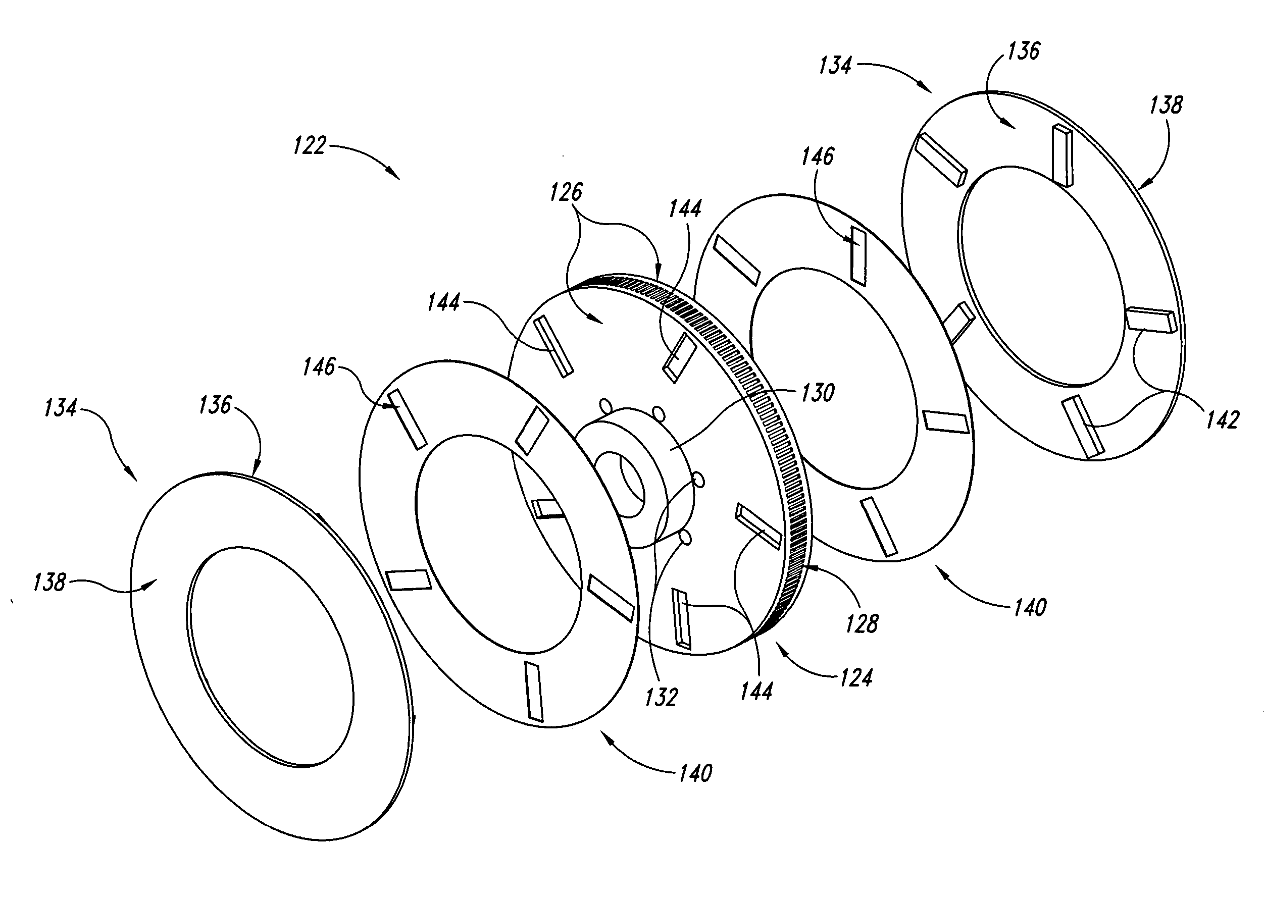
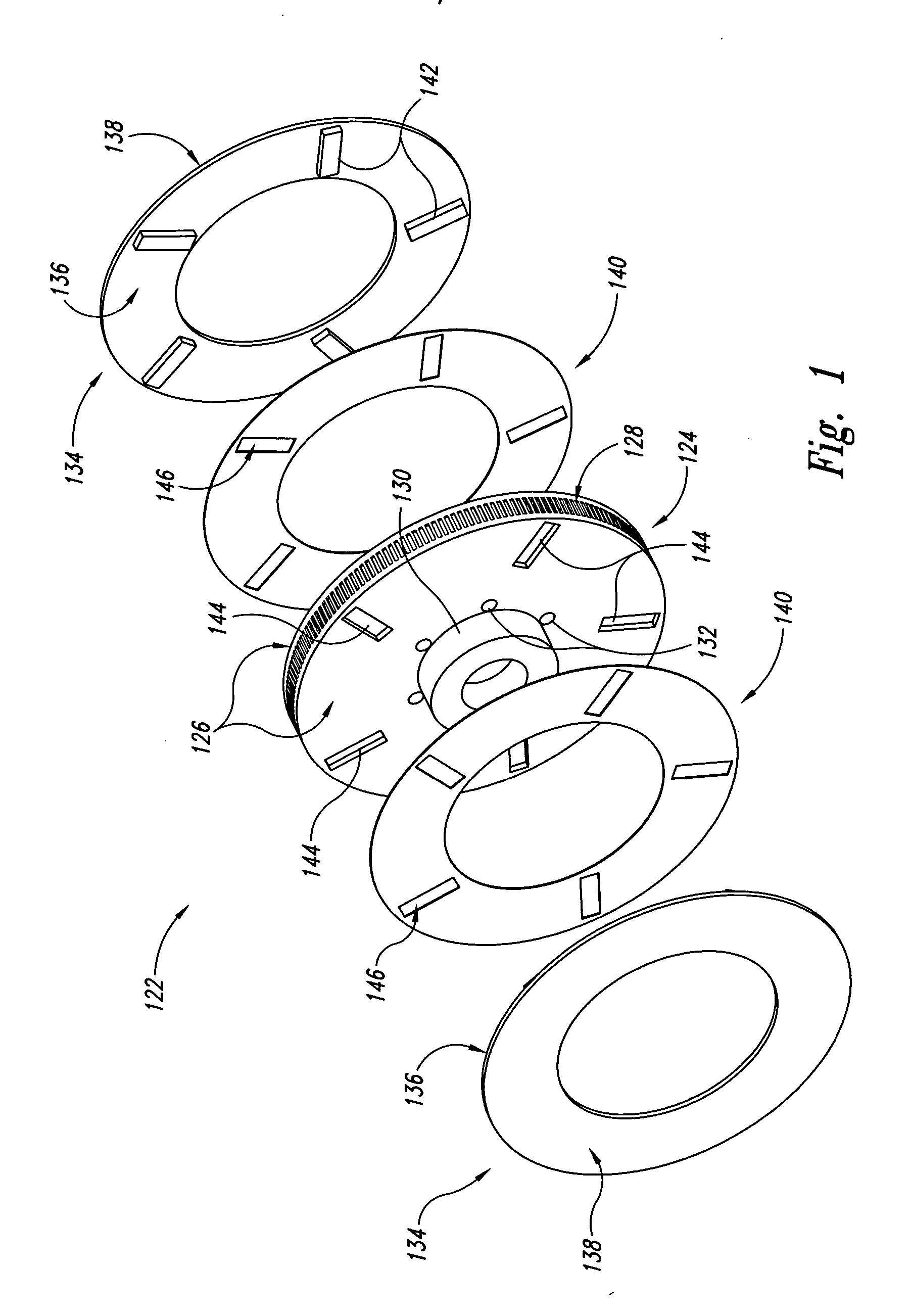
[0067] With reference to FIG. 1 and FIG. 4, a hydraulic press (pressure clamp) with a minimum of 15-ton capacity is used in the final assembly of components aligned or stacked in the following order: wear plate 134 (with interior surface 136 and projections 142 facing the bonding layer), bonding layer 140, outside surfaces of center rotor section 126, bonding layer 140, and wear plate 134 (with interior surface 136 and projections 142 facing bonding layer).

[0068] Alternatively the bonding layer 140 is flame-sprayed onto the interior surface 136 of the wear plates prior to alignment of the sprayed wear plates and the center rotor section.

[0069] Optional elements such as sensor devices, sensor materials or heat transfer-enhancing materials (e.g., sodium metal or carbon graphite foam) are placed into conforming recessed cavities 144 of the center rotor section as ...


PUM


Abstract

Novel composite disc brake rotor assemblies are provided, along with novel and efficient methods for manufacturing them. Preferably, the rotor assemblies comprise annular wear plates formed of particle reinforced aluminum-based metal matrix composite (MMC), ceramic matrix composite (CMC), or of ‘carbon graphite foam.’ The wear plates, made of a first material, are attached to annular surfaces of a central rotor, made of a second material, by fusing bonding layers between the wear plates and the rotor surfaces. The bonding layers are comprised of at least one of a metal alloy having a melting temperature lower than that of either the first or second materials, and a high-temperature adhesive. Preferably, the wear plates comprise projections that are positioned within adjacent receiving recesses in the center rotor. The bonding layers and projections enhance thermal and acoustical transference between the wear plates and the center rotor section. Carbon graphite foam provides for substantially enhanced heat transference. Use of the fusable binding layer, or adhesive provides for an efficient, low cost method of manufacturing for composite disc brake rotor assemblies.

Description

CROSS-REFERENCE TO RELATED APPLICATIONS [0001] This application claims the benefit of priority to U.S. Provisional Patent Application Ser. Nos. 60 / 558,761, filed 1 Apr. 2004, and 60 / 538,274, filed 21 Jan. 2004, both of which are incorporated by reference herein in their entirety.FIELD OF THE INVENTION [0002] The invention generally relates to vehicle brakes, and more particularly to novel light-weight disc brake rotor assemblies. BACKGROUND [0003] Conventional brake drums and brake disc rotors are manufactured from ductile iron, cast iron or steel. Such drums and rotors have mechanical and thermal properties sufficient to meet most practical requirements of drum and disc brake systems, but they are relatively heavy and adversely affect performance and fuel economy. [0004] Attempts have been made to reduce the weight of brake drums and brake discs by manufacturing them from lighter materials such as aluminum and aluminum alloys. However, while aluminum and aluminum alloys, such as ‘3...

Claims


Application Information

Patent Timeline
IPC IPC(8): F16D65/00F16D65/12F16D65/78F16D69/04
CPCF16D65/0006F16D65/12F16D66/02F16D69/04F16D2065/132F16D2200/0052F16D2069/0441F16D2069/0458F16D2069/0475F16D2200/0039F16D2065/1328
Inventor RAU, CHARLES BENJAMIN IIIJOLLEY, DALLAS W. JR.
Owner BENMAXX
Why Eureka
Try Eureka