Optical scanner control method, optical scanner and laser machining apparatus

a control method and optical scanner technology, applied in the direction of instruments, manufacturing tools, sensing by electromagnetic radiation, etc., can solve the problems of producing overshoot or overdamp at another angle, and the characteristic of optical scanners is not always uniform in this angle range, so as to achieve the effect of improving the speed of machining

Active Publication Date: 2005-08-25
HITACHI SEIKO LTD
View PDF8 Cites 13 Cited by
  • Summary
  • Abstract
  • Description
  • Claims
  • Application Information

AI Technical Summary

Benefits of technology

[0027] The mirror can be positioned at a high speed independently

Problems solved by technology

A optical scanner operates to rock a mirror within a limited angle range, but the characteristic of the optical scanner is not always uniform in this angle range.
That is, due to the torque constan

Method used


Image

  • Optical scanner control method, optical scanner and laser machining apparatus
  • Optical scanner control method, optical scanner and laser machining apparatus
  • Optical scanner control method, optical scanner and laser machining apparatus

Examples


Embodiment Construction

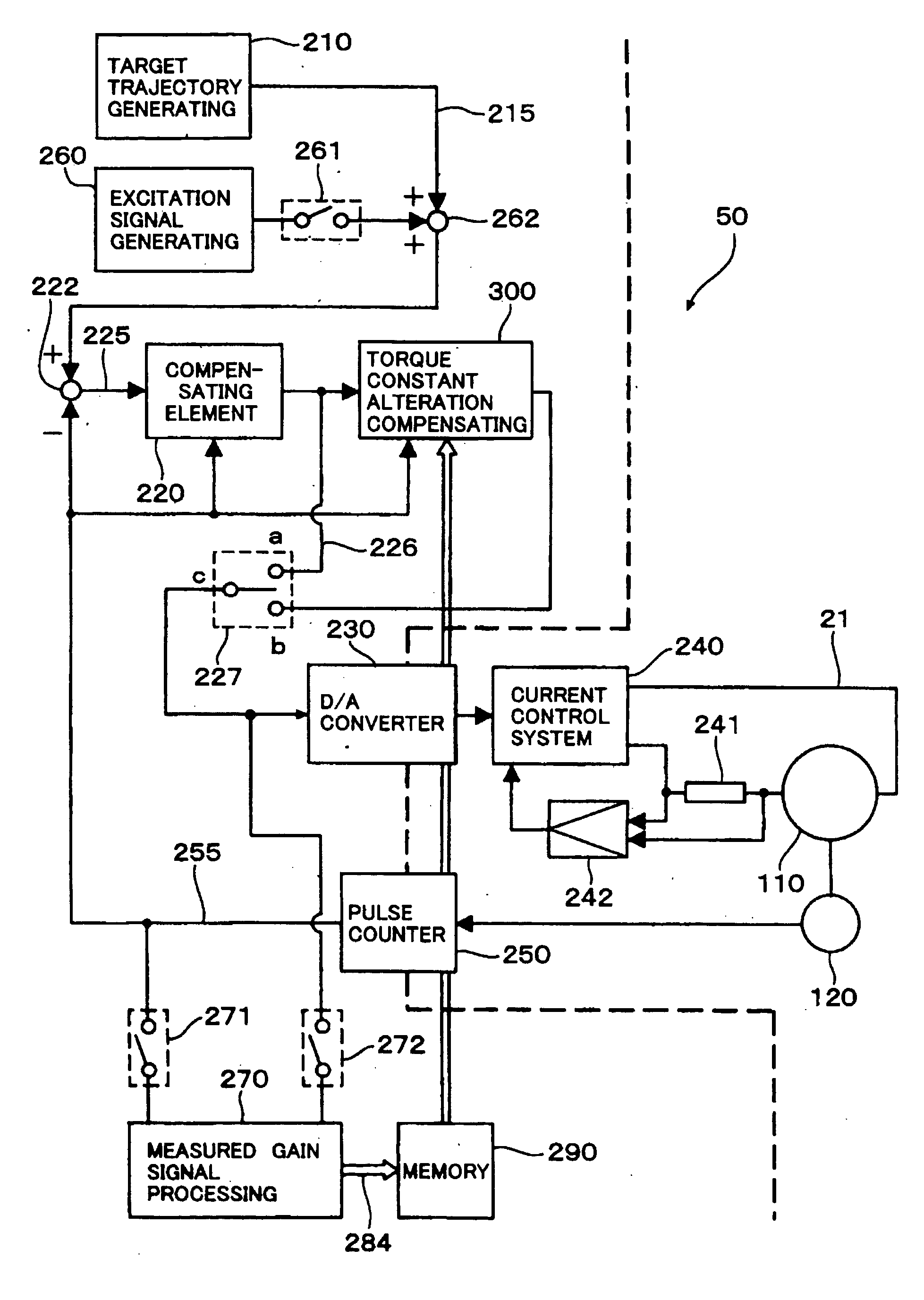
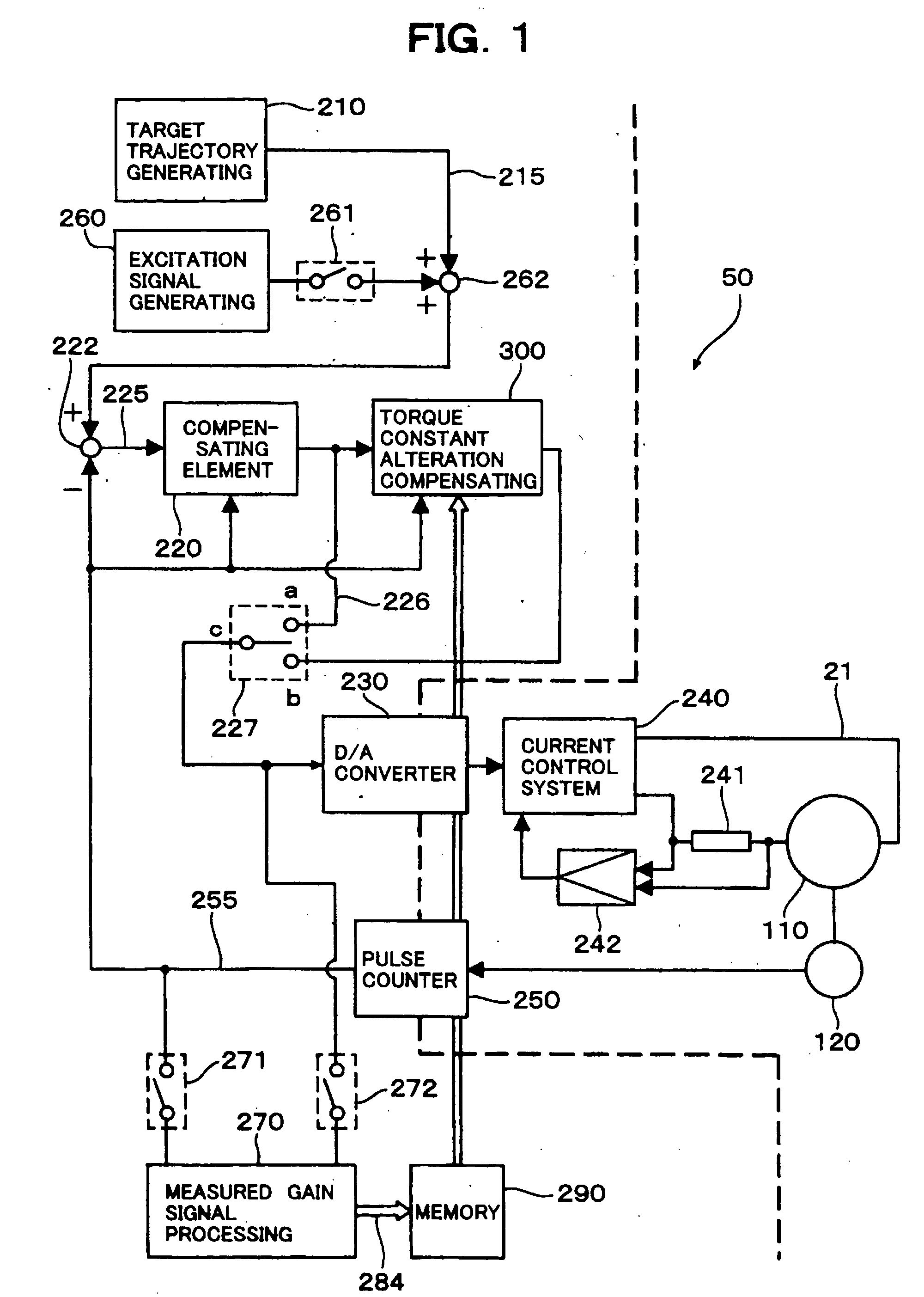
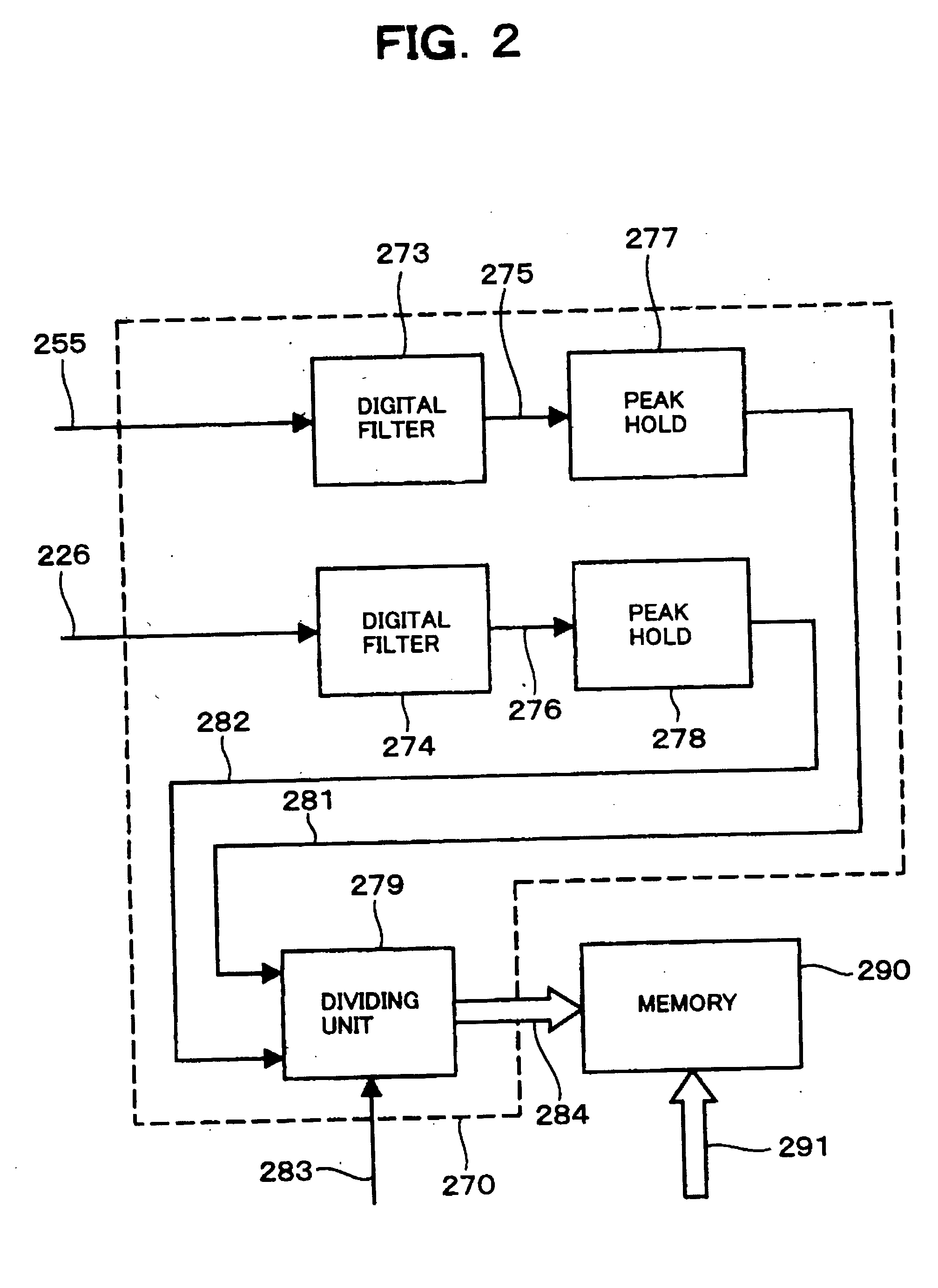
[0037]FIG. 1 is a block diagram of a scanner servo mechanism constituting a optical scanner control unit 50 having a torque constant measuring function according to the present invention. A portion to be executed by software with a servo processor is illustrated on the left of the broken line, and the connection relationship of hardware and the flow of signals are illustrated on the right. Incidentally, functions equivalent to those in FIG. 6 are referenced correspondingly, and redundant description thereof will be omitted. Though not shown, the optical scanner control unit 50 has a LAN interface such that the optical scanner control unit 50 can communicate with a remote host computer through a LAN.

[0038] An excitation signal generating unit 260 generates a sine-wave signal having a small amplitude. Here, the frequency of the sine wave is set to be away from resonance frequencies of a scanner actuator to be controlled, frequencies of various noises from amplifiers, a low frequency ...


PUM


Abstract

A optical scanner control method and a optical scanner capable of positioning a mirror at a high speed independently of a rocking angle, and a laser machining apparatus for irradiating a printed circuit board with a laser beam by use of the optical scanner to thereby perforate the printed circuit board. In order to operate an actuator for rocking the mirror based on a deviation of a current position from an commanded value, a change in gain of the actuator is measured in accordance with each rocking angle in advance, and the manipulated variable of the actuator is corrected to cancel the change in gain. Thus, the influence of the alteration of a torque constant in accordance with the rocking angle can be suppressed so that the response characteristic becomes uniform all over a scanning region, and the positioning speed can be improved.

Description

FIELD OF THE INVENTION [0001] The present invention relates to a optical scanner control method and a optical scanner for scanning lights such as laser beams, and a laser machining apparatus for irradiating a printed circuit board with laser beams by use of such a optical scanner so as to perforate the printed circuit board. BACKGROUND ART OF THE INVENTION [0002] A printed circuit board perforating laser machining apparatus as an example of a laser apparatus having a function of scanning with laser beams is an apparatus for irradiating a printed circuit board with pulsed laser beams so as to make holes for connecting conductor layers of the board with each other. For example, a background-art printed circuit board perforating laser machining apparatus has an XY table servo mechanism and a pair of optical scanner servo mechanisms (for example, see JP-A-2002-137074, page 2 and FIG. 6). A printed circuit board is mounted on the XY table servo mechanism and moved thereby in X- and Y-dir...

Claims


Application Information

Patent Timeline
IPC IPC(8): B23K26/00G02B5/08G02B7/182G02B26/00G02B26/10G02B26/12G06K7/10G06K7/14H05K3/00
CPCG02B26/105G02B7/1821B23K26/082
Inventor OTSUKI, HARUAKITOYAMA, SOUICHISEKI, KENTAOKUBO, YAICHIKITAMURA, DAISUKE
Owner HITACHI SEIKO LTD
Why Eureka
Try Eureka