Spark plug

Inactive Publication Date: 2005-08-25
NGK SPARK PLUG CO LTD
View PDF2 Cites 4 Cited by
  • Summary
  • Abstract
  • Description
  • Claims
  • Application Information

AI Technical Summary

Benefits of technology

[0013] Therefore, the spark plug of the invention is configured so that, in a virtual section which passes through a center of gravity of the second ground electrode, and which contains an axis of the spark plug, an included angle θ between a virtual line s1 and a virtual line s2 satisfies the following relationship of θ≧55°, the virtual line s1 passing through a middle point of the first discharge gap on the axis and making contact with the first ground electrode body, the virtual line s2 passing through the middle point of the first discharge gap and making contact with an outer side face of the second ground electrode. In the configuration in which the distance between the first ground electrode body and the second ground electrode is made large as described above, during the growth of a flame kernel produced in the vicinity of the middle point of the first discharge gap, the occurrence of the flame kernel contacting the second ground electrode and the first ground electrode body can be reduced. It is therefore possible to enable the flame kernel to efficiently grow and sufficiently improve the ignitability of the spark plug. When θ is smaller than 55°, the above-mentioned effect of allowing a flame kernel to efficiently grow is hardly obtained. By contrast, θ is preferably set so as not to be larger than 90°. When θ is larger than 90°, a failure such as overheating of the first ground electrode body or a fuel bridge may occur. As used herein, “included angle” means the acute angle formed by the virtual lines s1 and s2 such as that shown in FIG. 2 (the acute angle θ1 in FIG. 2).
[0014] In the spark plug of the invention, preferably, the included angle θ between the virtual line s1 and the virtual line s2 is θ≧60°. According to this configuration, the occurrence of a flame kernel contacting the second ground electrode and the first ground electrode body can be further reduced, and it is possible to enable the flame kernel to efficiently grow and more sufficiently improve ignitability of the spark plug.
[0015] In the spark plug of the invention, preferably, the first ground electrode body is configured so as to form a chamfered portion containing at least a contact point of an outer peripheral edge of the inner side face and the virtual line s1. According to this configuration, the distance between the first ground electrode body and the

Problems solved by technology

On the other hand, carbon or the like may adhere to the tip end face of the insulator to result in so-called “fouling.” In this case, spark discharge creeping on the surface of the insulator occurs in a second discharge gap which is formed by the second ground electrode and the side peripheral face of the center electrode.
Therefore, there is a possibility that the flame quenching

Method used


Image

  • Spark plug
  • Spark plug
  • Spark plug

Examples


examples

[0054] In order to demonstrate the effects of the invention, the following various experiments were conducted. However, the present invention should not be construed as being limited thereto.

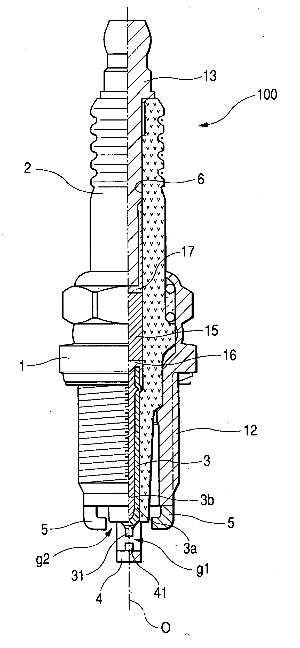
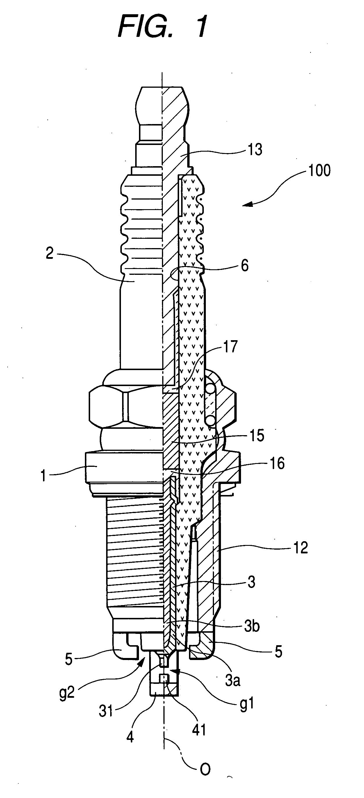
[0055] Various samples of the spark plug having the shape shown in FIGS. 1 and 2 were prepared in the following manner. First, sintered alumina ceramic was selected as the material of the insulator 2, INCONEL 600 as the electrode base member 3a of the center electrode 3, a copper core as the metal core 3b, INCONEL 600 as the first ground electrode body 4a, a heat-resistant Ni alloy (an alloy of Ni-90 wt % Ni) as the second ground electrode 5, Ir-20 wt % Rh as the material of the first noble metal tip 31, and Pt-20 wt % Ni as that of the second noble metal tip 41. The first noble metal tip 31 was formed as a cylindrical columnar shape having a diameter φ of 0.6 mm, and the second noble metal tip 41 was formed as a cylindrical columnar shape having a height t of 0.8 mm and a diameter φ of 0.6 mm....


PUM


Abstract

A spark plug including an insulator having an axial hole in an axial direction of the spark plug; a center electrode disposed in a tip end side of the axial hole of the insulator; a metal shell surrounding the insulator; a first ground electrode including a first ground electrode body having one end joined to the metal shell, and a noble metal tip joined to an inner side face of another end portion of the first ground electrode body and disposed opposite a tip end face of the center electrode across a first discharge gap. One end of the second ground electrode is bonded to the metal shell, and the another end is disposed opposite a side peripheral face of said center electrode or a side peripheral face of said insulator across a second discharge gap. Furthermore, the spark plug is characterized as having a distance t and an included angle θ as defined herein.

Description

BACKGROUND OF THE INVENTION [0001] 1. Field of the Invention [0002] The present invention relates to a spark plug used for providing ignition of an internal combustion engine. [0003] 2. Description of the Related Art [0004] A known spark plug for providing ignition of an internal combustion engine such as an automotive engine, comprises: an insulator having an axial hole in the axial direction of the spark plug, a center electrode disposed in a tip end side of the axial hole of the insulator; a metal shell surrounding the insulator; a first ground electrode in which one end is bonded to the metal shell and another end portion opposes a tip end face of the center electrode; and a second ground electrode in which one end is bonded to the metal shell, and another end opposes a side peripheral face of the center electrode or that of the insulator. In such a spark plug, spark discharge is caused in a first discharge gap formed by the center electrode and the first ground electrode to ign...

Claims


Application Information

Patent Timeline
IPC IPC(8): H01T13/32H01T13/46
CPCH01T13/467H01T13/32
Inventor KATO, TOMOAKI
Owner NGK SPARK PLUG CO LTD
Why Eureka
Try Eureka