
Method and apparatus for manufacturing carbon nanostructure, and carbon nanostructure assembly

Active Publication Date: 2013-11-14
SUMITOMO ELECTRIC IND LTD
View PDF1 Cites 5 Cited by
  • Summary
  • Abstract
  • Description
  • Claims
  • Application Information

AI Technical Summary

Benefits of technology

The invention is about a method for growing carbon nanostructures in the interface region between a catalyst and a separation member during chemical vapor deposition. By preliminary oxidation of the contact portion of the catalyst and the separation member, the carbon nanostructure can efficiently grow in the step of growing a carbon nanostructure. The invention also includes a holding member with a pair of holding portions that can easily handle carbon nanostructures with tension applied between the holding portions. The technical effects of the invention are improved efficiency and ease of handling carbon nanostructures for various applications.

Problems solved by technology

In the conventional method, however, a bend occurred in some cases at the carbon nanostructure grown from the catalyst.
It was difficult, however, to chuck a tip of the fine carbon nanostructure grown from the catalyst and apply a tension to the carbon nanostructure.

Method used


Image

  • Method and apparatus for manufacturing carbon nanostructure, and carbon nanostructure assembly
  • Method and apparatus for manufacturing carbon nanostructure, and carbon nanostructure assembly
  • Method and apparatus for manufacturing carbon nanostructure, and carbon nanostructure assembly

Examples


first embodiment

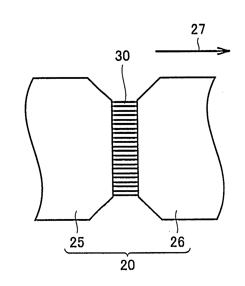
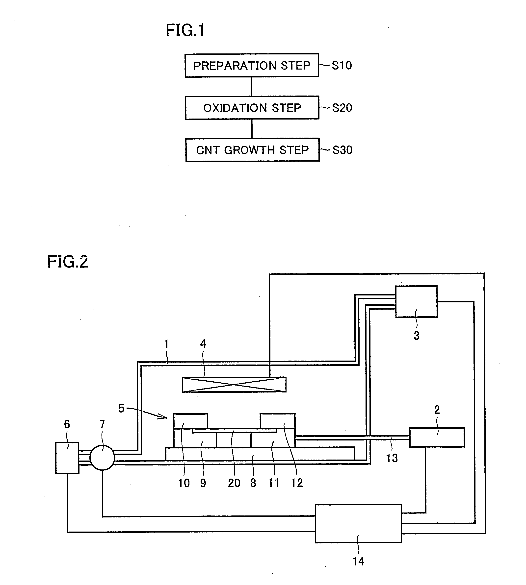
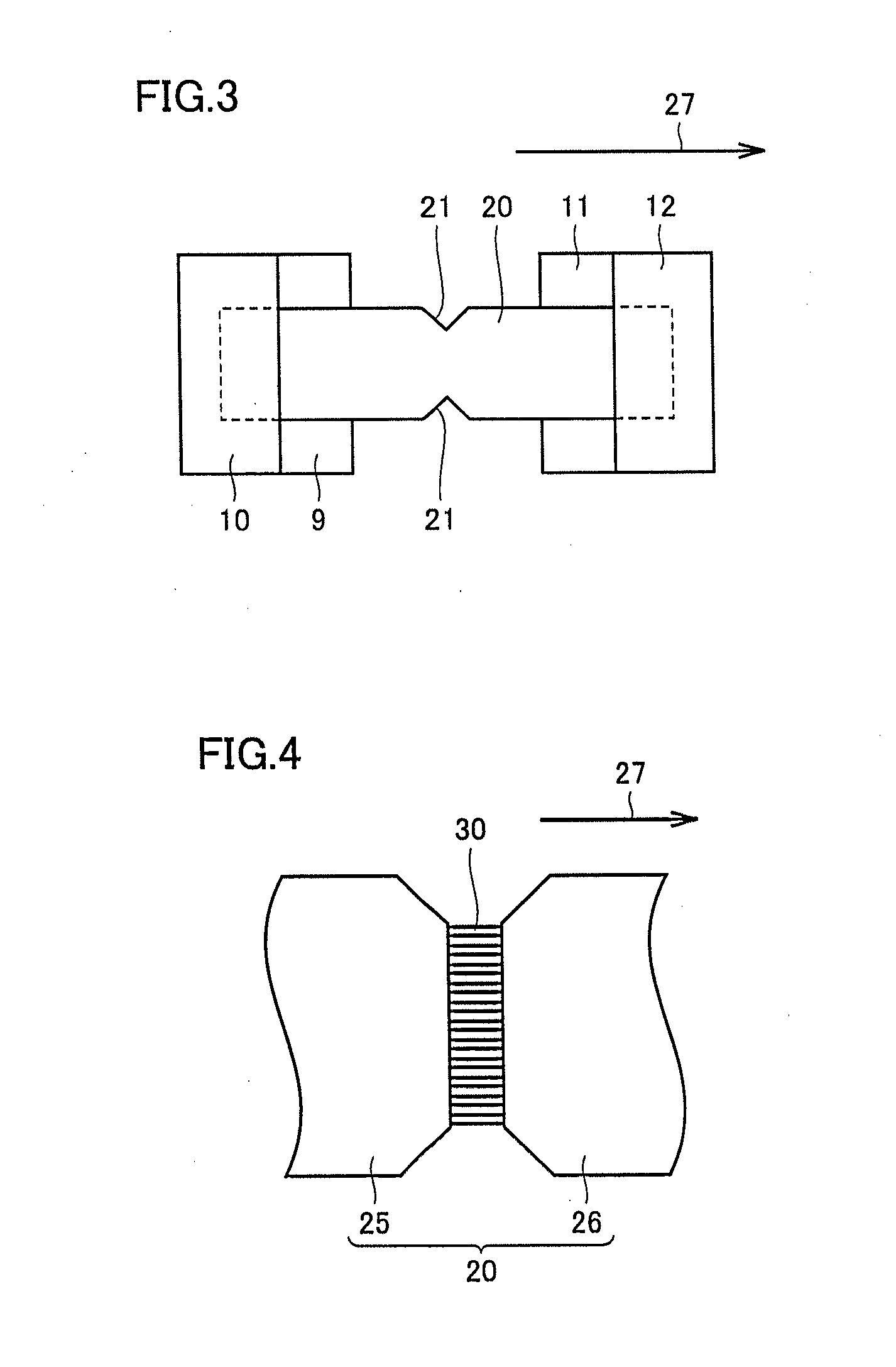
[0037]A method for manufacturing a carbon nanostructure according to a first embodiment of the present invention will be described with reference to FIGS. 1 to 4.

[0038]Referring to FIG. 1, in the method for manufacturing the carbon nanostructure according to the present invention, a preparation step (S10) is first performed. In this step (S10), a base body formed of a catalyst member including a catalyst and a separation member that are in contact with or integral with each other is prepared.

[0039]As shown in FIGS. 2 and 3, a metal sheet (metal foil) serving as a catalyst can be used as a base body 20. Pure iron, nickel, cobalt and the like can, for example, be used as the metal. A notch 21, which is a recessed portion for defining a position of fracture in a CNT growth step (S30) (refer to FIG. 1) described below, is preferably formed in base body 20. When the metal foil as shown in FIGS. 2 and 3 is used as base body 20, the metal foil forms the above-described catalyst member and ...

second embodiment

[0049]An apparatus for manufacturing a carbon nanostructure according to a second embodiment of the present invention will be described with reference to FIG. 5.

[0050]Referring to FIG. 5, the apparatus for manufacturing the carbon nanostructure includes reaction chamber 1, heating member 4 arranged outside reaction chamber 1, a diaphragm 31 connected to a catalyst member 35 forming base body 20 in order to hold catalyst member 35 at a position facing heating member 4, a separation member 36 arranged in contact with catalyst member 35, driving member 2 coupled to separation member 36 by coupling rod 13, the gas supply portion (not shown) for supplying the source gas and the like to reaction chamber 1, pump 7 and discharge portion 6 for discharging the gas from reaction chamber 1, and the controller (not shown) for controlling heating member 4, the gas supply portion, driving member 2, pump 7, and discharge portion 6. Catalyst member 35 has, for example, a circular planar shape, and d...

third embodiment

[0057]An apparatus for manufacturing a carbon nanostructure according to a third embodiment of the present invention will be described with reference to FIG. 7.

[0058]Referring to FIG. 7, the apparatus for manufacturing the carbon nanostructure basically includes a configuration similar to that of the apparatus for manufacturing the carbon nanostructure shown in FIG. 5, although the former is different from the latter in terms of a configuration of used base body 20. In other words, iron foil is used as catalyst member 35 forming base body 20, and separation member 36 is configured by a catalyst thin film 41 formed of an iron foil film, and two fixing members 42 and 43 for sandwiching and holding catalyst thin film 41. Separation member 36 is grasped by a grasp member 44. Grasp member 44 is connected to coupling rod 13.

[0059]Next, a method for manufacturing the carbon nanostructure using the apparatus for manufacturing the carbon nanostructure shown in FIG. 7 will be described. Altho...


PUM


Abstract

There is provided a method for manufacturing a carbon nanostructure with reduced occurrence of a bend and the like. The method for manufacturing a carbon nanostructure according to the present invention includes the steps of: preparing a base body formed of a catalyst member including a catalyst and a separation member that are in contact with or integral with each other (preparation step); oxidizing at least a part of a contact portion or integral portion of the catalyst member and the separation member (oxidation step); bringing a carbon-containing source gas into contact with the catalyst member and / or the separation member (CNT growth step); and growing a carbon nanostructure (CNT growth step). In the CNT growth step, the carbon nanostructure is grown in a separation interface region between the catalyst member and the separation member, by heating the base body while separating the separation member from the catalyst member.

Description

BACKGROUND OF THE INVENTION[0001]1. Field of the Invention[0002]The present invention relates to a method and an apparatus for manufacturing a carbon nanostructure, and a carbon nanostructure assembly, and more particularly to a method and an apparatus for manufacturing a carbon nanostructure that extends in one direction, and a carbon nanostructure assembly.[0003]2. Description of the Background Art[0004]Conventionally, there has been known a carbon nanostructure including a linear structure in which carbon atoms are aligned in a nanometer-level diameter and a sheet-like structure constituted by carbon atoms and having a nanometer-level thickness, which are typified by carbon nanotube, graphene and the like. As a method for manufacturing such carbon nanostructure, there has been proposed a method for supplying a carbon-containing source gas to a heated fine catalyst, thereby growing a carbon nanostructure from the catalyst (refer to, for example, Japanese Patent Laying-Open No. 200...

Claims


Application Information

Patent Timeline
IPC IPC(8): C01B31/02B01J19/00
CPCC01B31/0226B01J19/00B01J4/008B01J15/005B01J19/1887B01J2219/00058B01J2219/00135B82Y30/00B82Y40/00C01B32/16Y10T428/19
Inventor HIKATA, TAKESHIOKUBO, SOICHIROUTSUNOMIYA, RISAHIGASHI, YUGO
Owner SUMITOMO ELECTRIC IND LTD
Learn More