Optical device and projector

a technology of optical modulator and projector, which is applied in the direction of projectors, color television details, instruments, etc., can solve the problems of small temperature difference between the optical modulator and the cooling fluid, difficult to efficiently cool the optical modulator, and heat generation on the polarization plate, etc., to achieve high heat value, high heat value, and high heat value

Inactive Publication Date: 2005-08-25
SEIKO EPSON CORP
View PDF4 Cites 13 Cited by
  • Summary
  • Abstract
  • Description
  • Claims
  • Application Information

AI Technical Summary

Benefits of technology

[0027] According to the present invention, for instance, a pressure-feed section dedicated to feed the cooling fluid to a predetermined optical modulator holder holding the optical modulator with high heat value can be provided. Thus, the flow volume of the cooling fluid fed to the predetermined optical modulator holder holding the optical modulator with high heat value can be adjusted, so that the optical modulator with high heat value can be efficiently cooled. For instance, by arranging the flow volume of the cooling fluid fed by the dedicated pressure-feed section to be larger than that of the cooling fluid fed by the other pressure-feed sections, cooling efficiency of the optical modulator with high heat value can be further enhanced without providing the flow volume changer or changing the tube diameter of the fluid circulators or sectional area of the flow paths, and therefore, the respective optical modulators can be efficiently cooled.
[0028] With the above arrangement, the optical modulator with high heat value can be cooled, which is applicable to increased luminance and increased heat density resulted from downsizing, so that merchantability can be enhanced.

Problems solved by technology

Further, among the light beams irradiated from the light source and transmitted through the liquid crystal panel, the light beam not having the predetermined optical axis is absorbed by the polarization plate, which easily causes generation of heat on the polarization plates.
Therefore, temperature difference between the optical modulator and the cooling fluid becomes small, which makes it difficult to cool the optical modulator efficiently.

Method used


Image

  • Optical device and projector
  • Optical device and projector
  • Optical device and projector

Examples


first exemplary embodiment

[0054] A first exemplary embodiment of the present invention will be described below with reference to the attached drawings.

[1] Arrangement of Projector

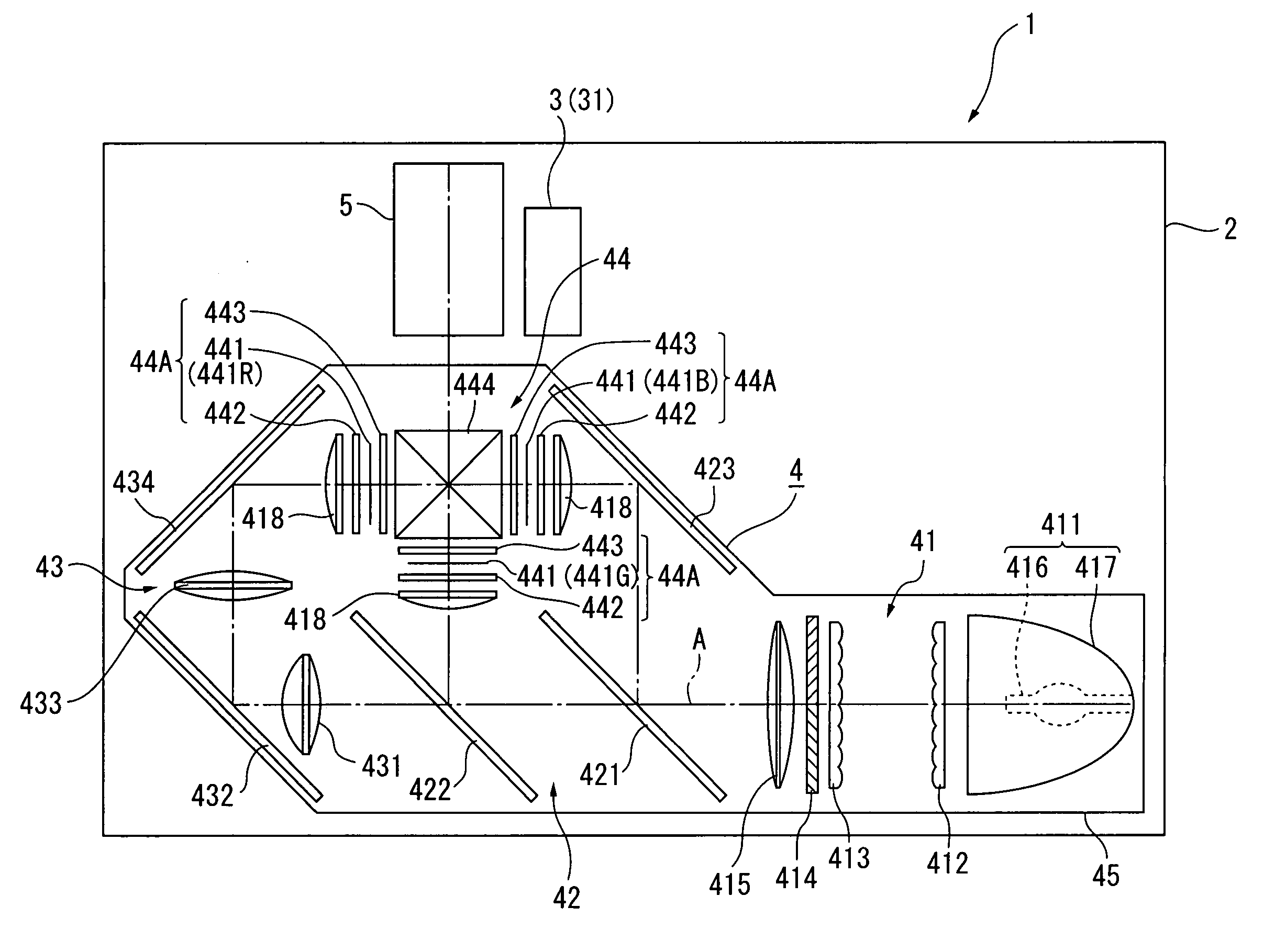
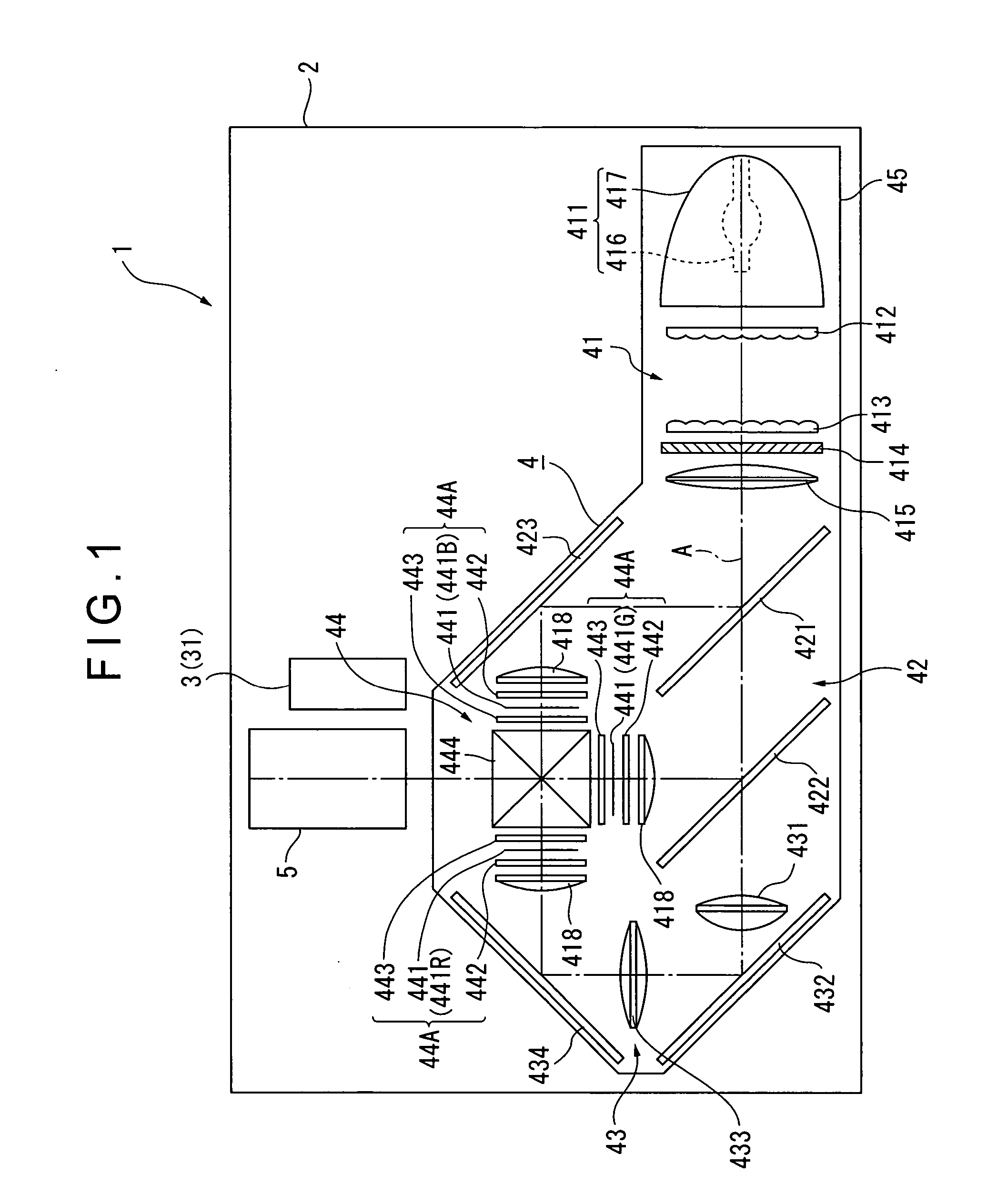
[0055]FIG. 1 is a schematic illustration showing the outline of a projector 1.

[0056] The projector 1 modulates a light beam irradiated from a light source in accordance with image information to form a color image, and projects the formed color image on a screen in an enlarged manner. The projector 1 includes an exterior case 2, a cooling unit 3, an optical unit 4 and a projection lens 5 as a projection optical device.

[0057] In FIG. 1, although not shown, a power source block, a lamp driving circuit and the like are disposed in a space not occupied by the cooling unit 3, the optical unit 4 and the projection lens 5 in the exterior case 2.

[0058] The exterior case 2 is made of synthetic resin or the like, and formed in a substantially rectangular parallelepiped with the cooling unit 3, the optical unit 4 and the projection lens ...

second exemplary embodiment

[0164] A second exemplary embodiment of the present invention will be described below with reference to the attached drawings.

[0165] In the following description, the same components as those in the first exemplary embodiment are indicated by the same reference symbols or numerals for omitting or simplifying the detailed description thereof.

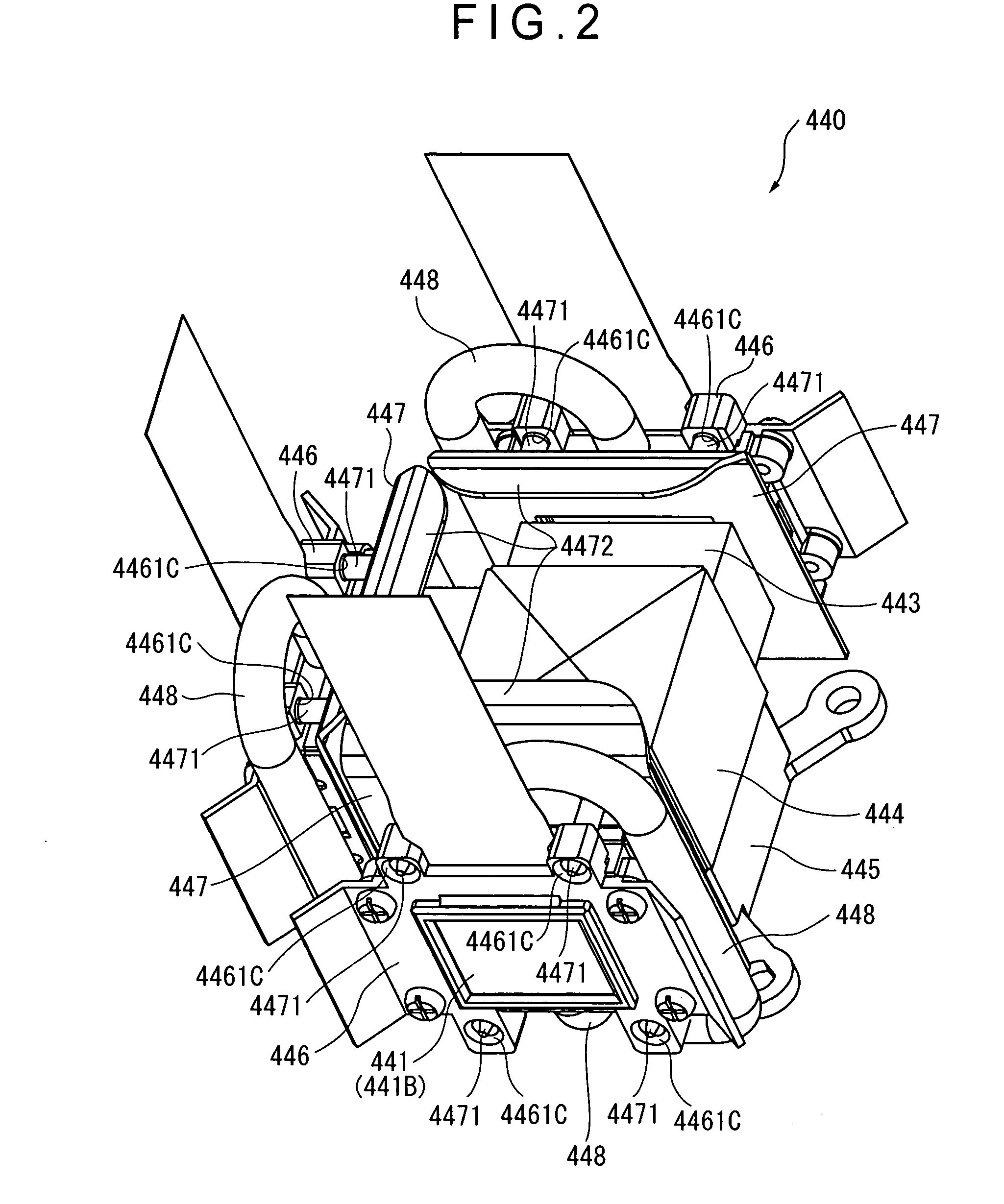
[0166] In the above first exemplary embodiment, the optical device body 440 includes the three volume changers 449 capable of changing the flow volumes of the cooling fluid introduced into the respective optical modulator holders 446. By operating the respective adjusting screws 449B1 of the respective volume changers 449, the flow volume of the cooling fluid introduced into the respective cooling chambers R1 can be changed.

[0167] On the other hand, in the second exemplary embodiment, by providing different tube diameters to each of cooling fluid inflow sections 5451 and each of cooling fluid outflow sections 5452 of a fluid branch section 545...

third exemplary embodiment

[0173] A third exemplary embodiment of the present invention will be described below with reference to the attached drawings.

[0174] In the following description, the same components as those in the first exemplary embodiment are indicated by the same reference symbols or numerals for omitting or simplifying the detailed description thereof.

[0175] In the first exemplary embodiment described above, in the optical device body 440, the cooling fluid circulates in the flow path from the fluid branch section 445 to the optical modulator holder 446 and back to the fluid branch section 445 through the plurality of fluid circulators 448 by natural convection.

[0176] On the other hand, in the third exemplary embodiment, the arrangement of an optical device body 640 differs from that of the first exemplary embodiment, where the cooling fluid is circulated forcibly. The arrangement in the third exemplary embodiment is substantially the same as that of the first exemplary embodiment except the...


PUM


Abstract

An optical device body (440) includes: three optical modulator holders (446) respectively holding three liquid crystal panels (441) and having cooling chambers with cooling fluid sealed therein to respectively cool the three liquid crystal panels (441) with the cooling fluid in the respective cooling chambers; a plurality of fluid circulators (448) intercommunicated with the three optical modulator holders (446) to guide the cooling fluid to the outside of the respective cooling chambers and re-introduce the cooling fluid into the respective cooling chambers; and a flow volume changer (449) disposed in a flow path of the cooling fluid and capable of changing flow volumes of the cooling fluid flown into the respective optical modulator holders (446) in accordance with heat values of the three liquid crystal panels (441).

Description

BACKGROUND OF THE INVENTION [0001] 1. Field of the Invention [0002] The present invention relates to an optical device and a projector. [0003] 2. Description of Related Art [0004] Conventionally, there has been known a projector having a plurality of optical modulators that modulate a light beam irradiated from a light source in accordance with image information to form an optical image, a color-combining optical device that combines and irradiates the light beam modulated by the optical modulator, and a projection optical device that projects the light beam combined by the color-combining optical device in an enlarged manner. [0005] As the optical modulator, for instance, an arrangement including an active matrix driven liquid crystal panel that has an electrooptic material such as a liquid crystal sealed between a pair of boards, and a polarization plate that only transmits light beams having a predetermined optical axis is widely used. [0006] Specifically, the pair of boards incl...

Claims


Application Information

Patent Timeline
Patent Type & Authority Applications(United States)
IPC IPC(8): G03B21/16G03B21/26H04N9/31
CPCH04N9/3197H04N9/3144
Inventor FUJIMORI, MOTOYUKIMURATA, MASAMI
Owner SEIKO EPSON CORP
Why Eureka
Try Eureka