[0008] The present invention has for its primary object to resolve the major problems as stated earlier, and to make a further development of the roller bearing cage disclosed in the senior application of common assignment, which is recited earlier in “background of the invention”, to provide a roller bearing cage well applicable to the high-compression, high-speed engine, with more inexpensive production costs. The constructional features of the present invention reside in a turning operation on the lathe at the initial step to generate a cage blank, and a configuration of the cage with inside
retainer projections unique in construction finished using a rolling operation other than the turning operation. More particularly the present invention is to provide a roller bearing cage favorable for the bearings, which are needed to stand up to the harsh conditions imposed by advanced high-compression, high-speed engine, and also to provide a production method of a roller bearing cage with using a rolling operation, which is substantially more friendly to the environment because of conserving row stock of material while
cutting hours to make the desired bearing cage, and also because of the absence of the formation of chips. Thus, the production method according to the present invention makes it possible to provide inexpensively the desired roller bearing cage from basic minimum quantity of row material.
[0015] The present invention is further concerned with a method of producing a roller bearing cage comprising steps of; shearing a tubular material into a ring-like blank;
processing the ring-like blank by rolling operation into a rolled product of cage contour where there is formed a circular inside recess of semicircular contour in transverse section in axial direction of the cage; working the rolled product by
punching operation so as to have more than one pocket for receiving the roller therein, which are spaced circularly away from one another; further working the punched product with pockets into a formed product in which raised ridges are made on the pillars between two adjoining pockets preparatory to the inside
retainer lips to keep the rollers against falling away from the cage;
processing the formed product by turning operation to face flat surfaces on the axially opposite sides of the formed product, yielding a turned product; heating the turned product into a heat-treated product high in durability; further working the heat-treated product by turning operation to finish a circular outside surface thereof into a final form of a prescribed outside circumferential dimension; and
processing the turned product of the prescribed outside circumferential dimension by surface treatment to provide a finished cage enhanced in durability.
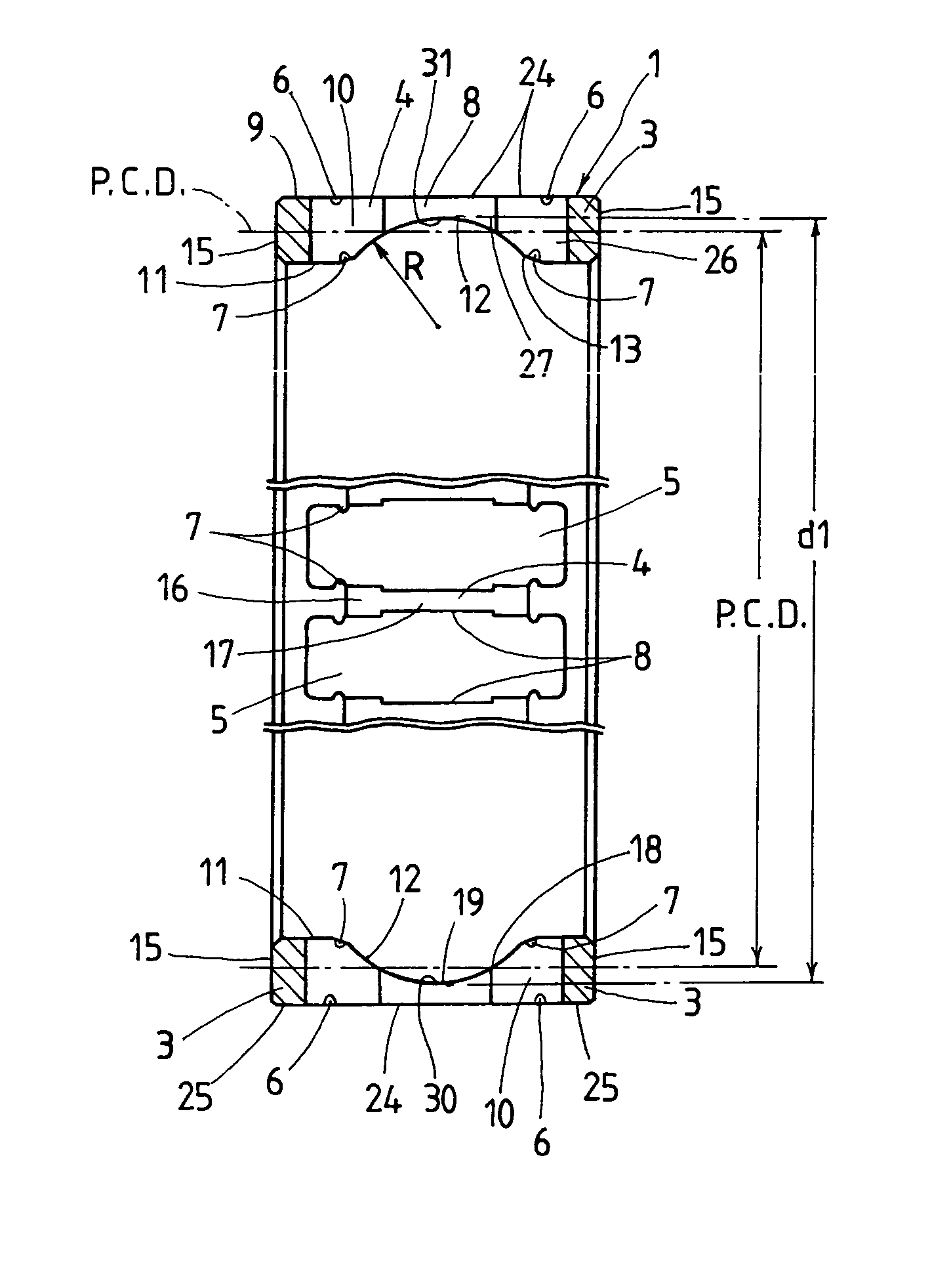
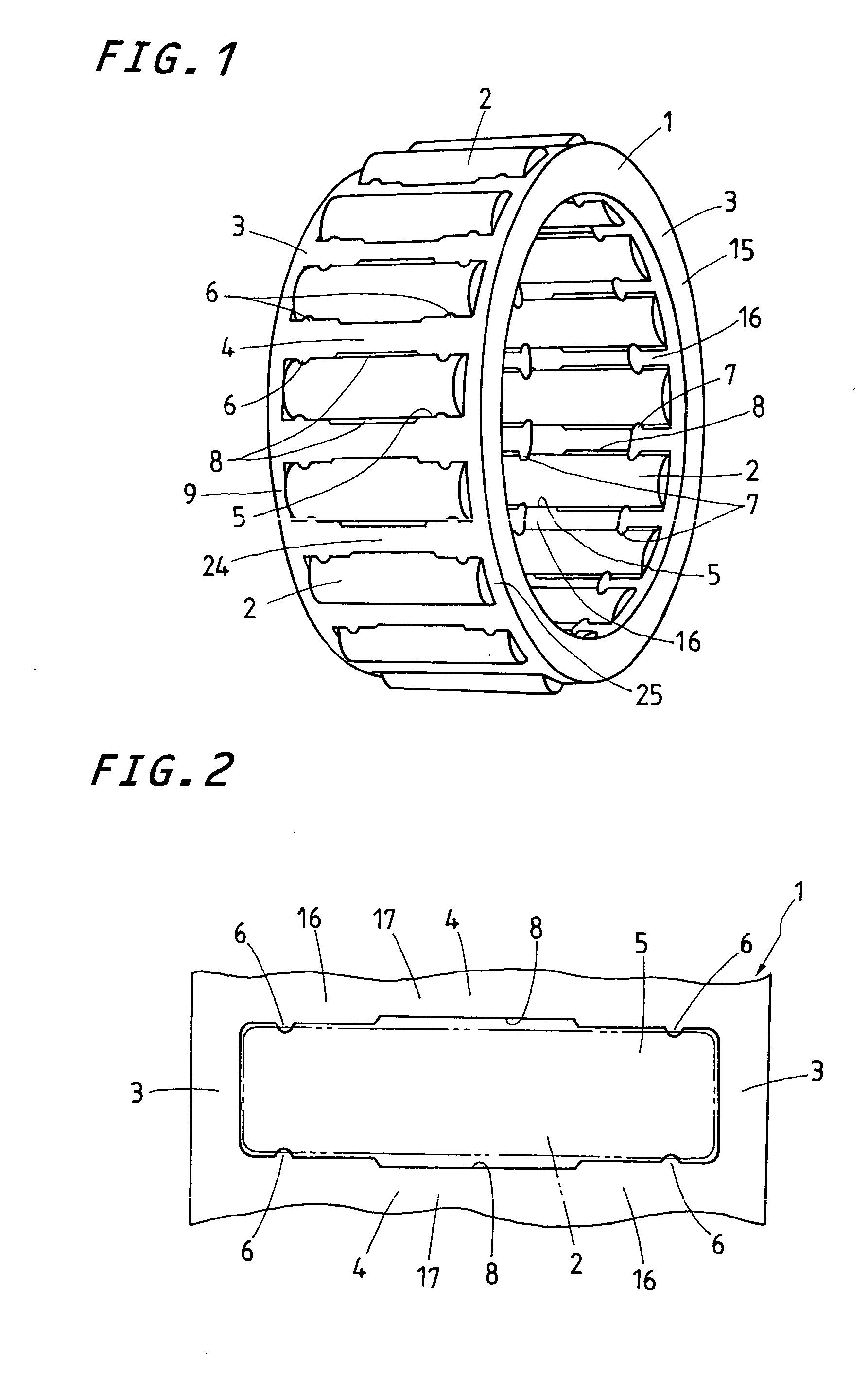
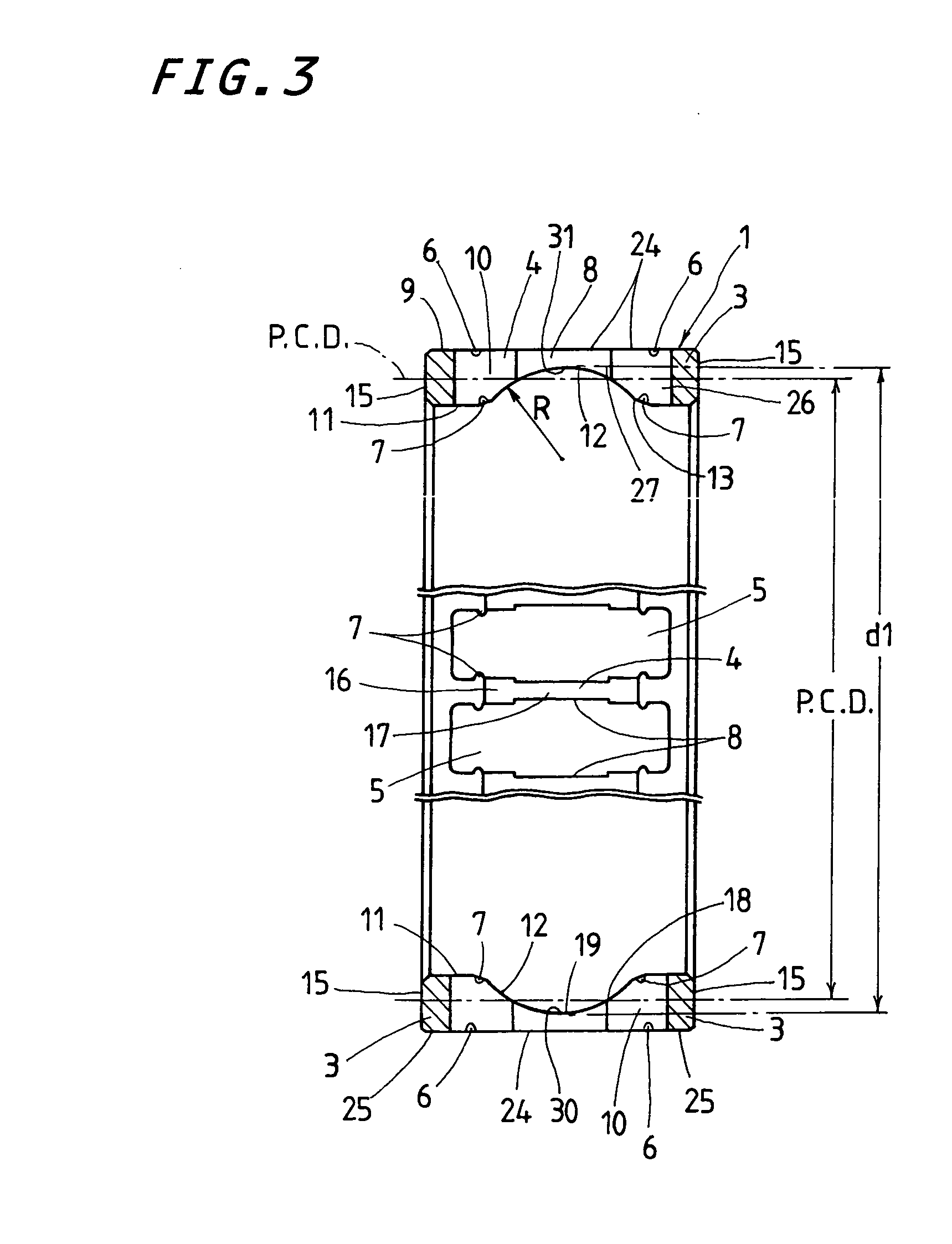
[0017] With the roller bearing cage constructed as stated earlier, the circular inside recess made around the circular inside surface of the cage is formed to have the concaved surface that is easier to work it by any one of the turning operation and the rolling operation, even with inexpensive production cost. The roller bearing cage of the present invention is expected to display desired performance tolerant to the high-speed engines when installed in the rod “big-end” of the connecting rod of the engine. The roller bearing cage of the present invention is envisaged making the surface-to-surface contact stress more uniform across the overall circular outside surface of the cage, and also rendering the cage less in weight to reduce the surface-to-surface contact stress that might be exerted on the cage. Since the rollers are kept in the cage with the outside and inside retainer lips for
free rotation, but against falling away out of the cage whether inside or outside, the roller bearing cage making sure of keeping the rollers against falling away is much easier to
handle it upon installation of the roller bearing cage into
mating connecting rod in the engine. The roller bearing cage, as undergoing revolving force as well as
centrifugal force, is born or guided predominantly on the circular outside surface of the cage. The cage recessed around the circular inside surface thereof to have the concaved surface helps stave off any locally lopsided surface-to-surface contact stress, which might otherwise occur on the circular outside surface of the cage, and also render the weight of the cage as small as possible, lessening the surface-to-surface contact stress imparted on the cage. As a result, the roller bearing cage of the present invention is more tolerant to the high revolution of the engine, compared with the prior roller bearing cage.
[0018] The roller bearing cage in which the cage is processed with using a rolling operation present invention may be provided inexpensively from basic minimum quantity of row material, compared with the cage worked on the lathes by the turning operation. The rolling operation where the
circular surface inside the cage blank is subjected to the compressive working by rolls is preferable to ensure the strength and stiffness of the cage, and substantially more friendly to the environment because of the absence of the formation of chips. With the roller bearing cage constructed as stated earlier, the circular inside surface of the cage is designed into the specific contour, which would be worked easily by the rolling operation, more particular, the concaved surface semicircular in transverse section in the axial direction of the cage. Moreover, the inside retainer lips
lying in flush with circular inside surface of the cage are preferable for the rolling operation and also result in such construction that they are hard to make any engagement with their associated rollers, which might worsen the engine performance.
[0019] According to the present invention, consequently, the roller bearing cage improved in performances including stiffness, strength, and so on of the cage itself may be provided from basic minimum quantity of row material, with using the working operation that is substantially more friendly to the environment and more expensively because of conserving row stock of material while
cutting hours to make the desired bearing cage, and also because of the absence of the formation of chips. In forming the inside retainer lips to the cage for the roller bearing cage according to the present invention, inside raised ridges are first formed simultaneously with the rolling operation and, then, the inside raised ridges are easily finished by the pressing operation into the inside lips that are flush with the circular inside surface of the cage. The construction in which the inside retainer lips are made flush with the circular inside surface of the cage helps render the rollers harder to make any engagement with the inside retainer lips, compared with the prior roller bearing cage. The constructional feature that the rollers are hard to make engagement with the inside retainer lips results in keeping the cage against any occurrence of
seizing during high revolution of the engines, realizing improvement in engine performance.
