PEM fuel cell stack with floating current collector plates

a fuel cell and collector plate technology, applied in the field of electrochemical fuel cell stacks, can solve the problems of inconvenient and intruding wire connectors, inconvenient and inconvenient design of edge current collectors, and inconvenient and inconvenient electrical contact between the two designs, so as to minimize the electrical contact resistance therebetween

Inactive Publication Date: 2005-08-25
PALCAN POWER SYST
View PDF9 Cites 29 Cited by
  • Summary
  • Abstract
  • Description
  • Claims
  • Application Information

AI Technical Summary

Benefits of technology

[0016] According to another aspect of the invention, there is provided an end plate assembly for a proton exchange membrane fuel cell stack, comprising: an end plate having means for physically coupling the end plate to another end plate such that pressure is applied to a fuel cell stack sandwiched between the end plates; a current collector comprising an elec

Problems solved by technology

Both designs have noticeable drawbacks for practical industrial applications.
The edge current collector design has inconvenient and intr

Method used


Image

  • PEM fuel cell stack with floating current collector plates
  • PEM fuel cell stack with floating current collector plates
  • PEM fuel cell stack with floating current collector plates

Examples


Embodiment Construction

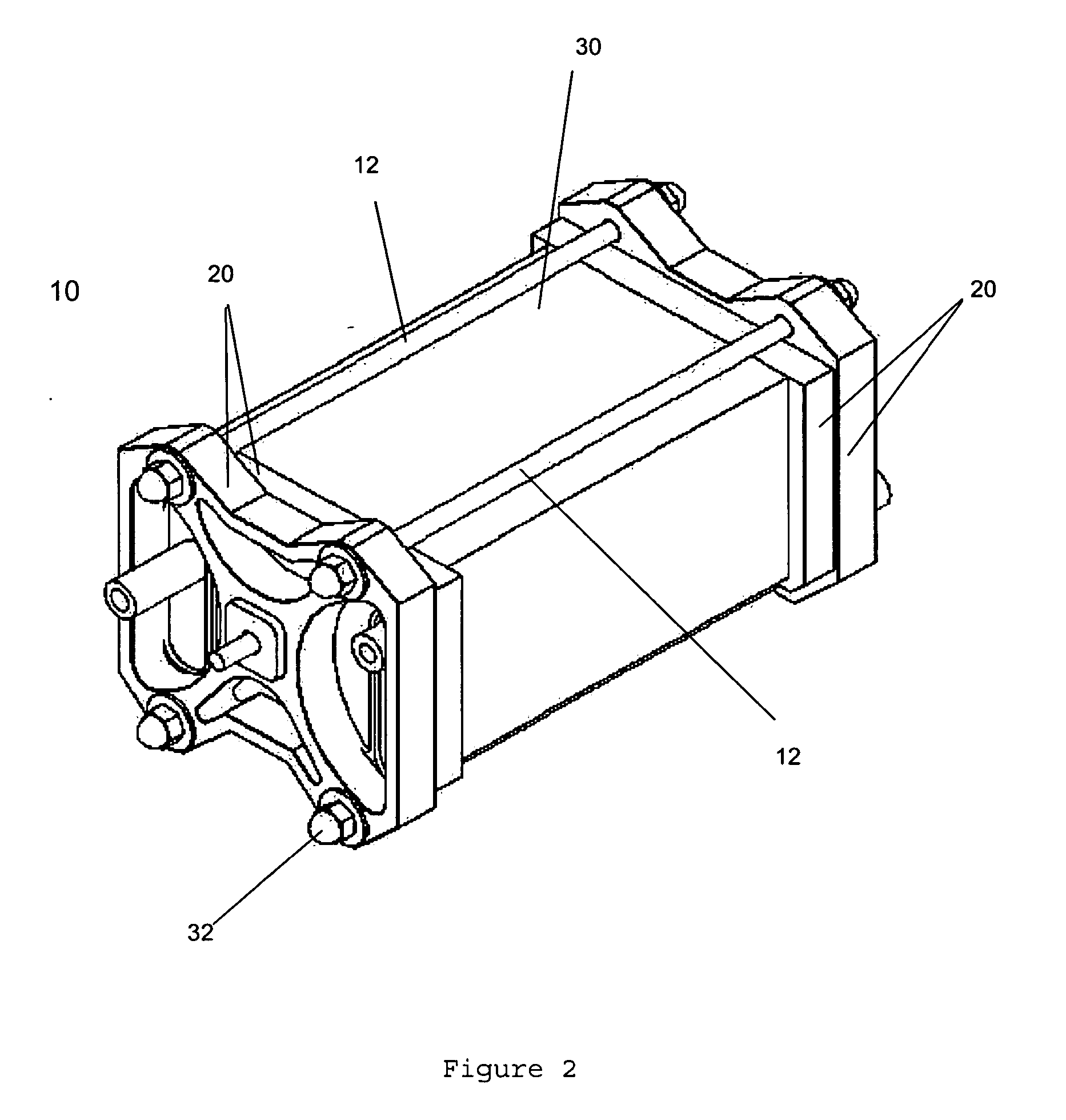
[0023] Referring to FIG. 2 and according to one embodiment of the invention, a fuel cell stack assembly 10 comprises a pair of fuel cell end plate assemblies 20 sandwiching multiple fuel cells 30 (shown as a single block in FIG. 2). Tie rods 12 are fastened at each end to an end plate assembly 20 by spring-loaded tie rod nuts 32, thereby physically connecting the end plate assemblies 20 together; a selected pressure can be applied to the fuel cells 30 by selective adjustment of the tie rod nuts 32.

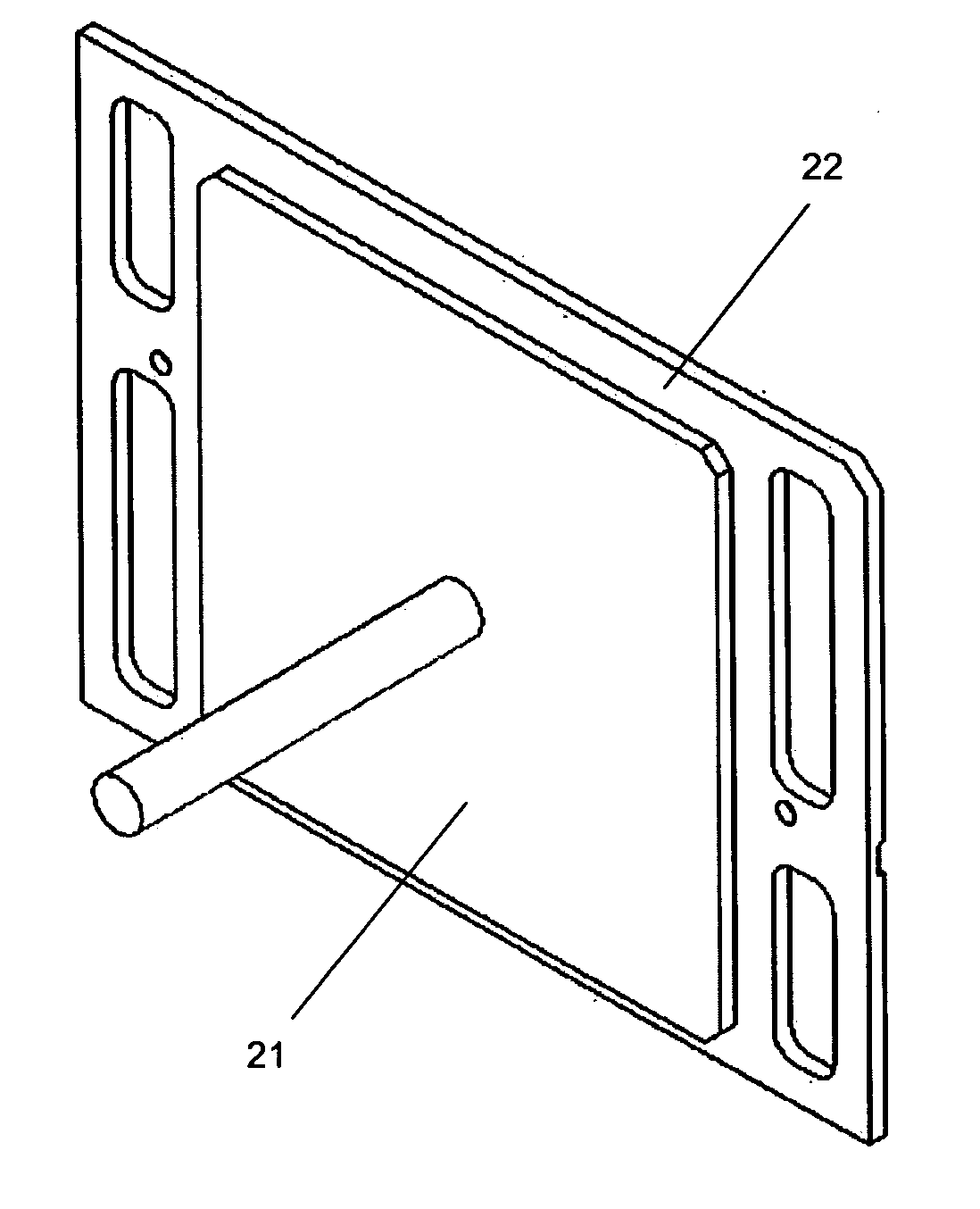
[0024] Referring to FIG. 3, each end plate assembly 20 comprises a current collector 21; an elastic pad 23; a current and gas insulator 24; an end plate 25; a current collector retention nut 26, and seals 27. The components 21, 23, 24, 25, 26, and 27 of the end plate assembly 20 cooperate in such a way that minimizes the electrical contact resistance between an end (first or last) fluid flow field plate 22 of the fuel cell stack 10 and the current collector 21. This is accomplished by arr...


PUM


Abstract

A proton exchange membrane (PEM) fuel cell end plate assembly provides an axial direction electric lead on an end plate of the assembly, and minimizes the contact resistance between an end fluid separator plate of a fuel cell stack and a current collector of the assembly. The current collector comprises an electrically conductive flat plate and a solid member connected together. The member goes through an opening on the end plate and provides an axial direction electric lead from the fuel cell stack. Means are provided to firmly contact the current collector and the fluid separator plate to maintain good contact across the entire area between the two components. The means of firmly contacting include moulding or bonding the separator plate and current collector together, or applying pressure to the separator plate and current collector such that firm contact is maintained between the two components.

Description

CROSS-REFERENCE TO RELATED APPLICATION [0001] This application claims the benefit of U.S. Provisional Patent Application No. 60 / 535,509, filed Jan. 12, 2004.FIELD OF THE INVENTION [0002] This invention relates generally to electrochemical fuel cell stacks and, more particularly, to proton-exchange-membrane (“PEM”) fuel cell stacks. BACKGROUND OF THE INVENTION [0003] Electrochemical fuel cells convert fuel and an oxidant to electricity and a reaction product. In electrochemical fuel cells employing hydrogen as the fuel and oxygen or air as the oxidant, the reaction product is water. Solid polymer fuel cells generally include a membrane electrode assembly (“MEA”) layer comprising a solid polymer electrolyte or ion exchange membrane disposed between two electrode layers. The electrode layers typically comprise porous, electrically conductive sheet material and an electrocatalyst at each membrane-electrode interface to promote the desired electrochemical reaction. [0004] At the anode, t...

Claims


Application Information

Patent Timeline
IPC IPC(8): H01M2/08H01M8/02H01M8/10
CPCH01M8/0247H01M8/0276Y02E60/50H01M8/248H01M2008/1095H01M8/0297
Inventor BELANGER, RAYMONDSHEN, JOHN JIANYUEDONG, ZUOMINTOMLINSON, JEREMY JOHN
Owner PALCAN POWER SYST
Why Eureka
Try Eureka