Hydrogen storage system materials and methods including hydrides and hydroxides

a technology of hydrogen storage system and hydrogen storage material, applied in the direction of metal hydrides, metal hydrides, alkali/alkaline-earth/beryllium/magnesium hydrides, etc., can solve the problems of limited selection of relatively light weight hydrogen storage material, and limited hydrogen storage material selection

Inactive Publication Date: 2005-09-01
GM GLOBAL TECH OPERATIONS LLC
View PDF18 Cites 18 Cited by
  • Summary
  • Abstract
  • Description
  • Claims
  • Application Information

AI Technical Summary

Problems solved by technology

Pressurization and liquification require relatively expensive processing and storage equipment.
Presently, the selection of relatively light weight hydrogen storage material is essentially limited to magnesium and magnesium-based alloys which provide hydrogen storage capacity of several weight percent, essentially the...

Method used


Image

  • Hydrogen storage system materials and methods including hydrides and hydroxides
  • Hydrogen storage system materials and methods including hydrides and hydroxides
  • Hydrogen storage system materials and methods including hydrides and hydroxides

Examples


example 1

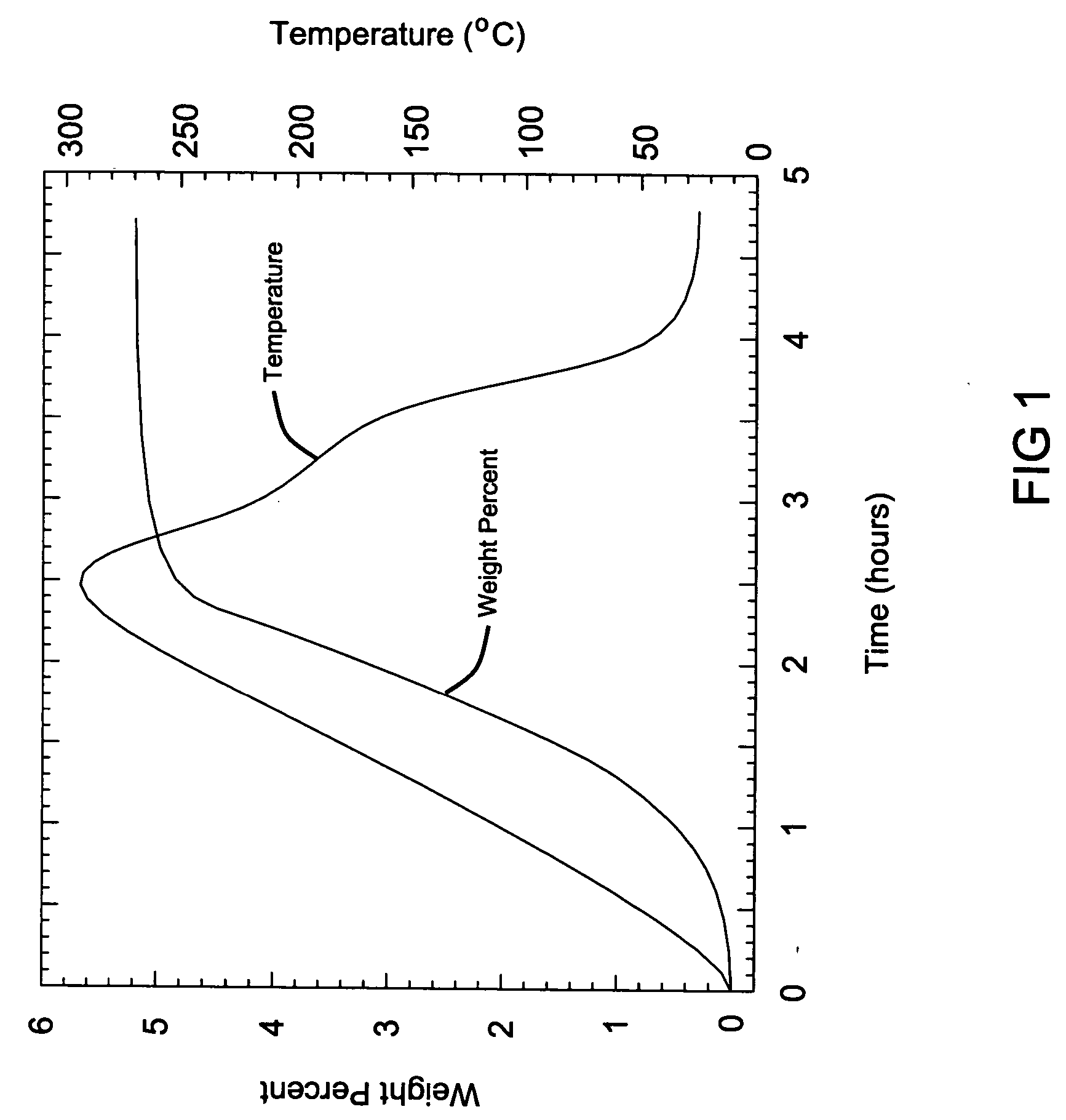
[0064] This example demonstrates the hydrogen storage material system where MI and MII are selected to be lithium in the hydrogen storage material system. An equal molar ratio of lithium hydride (LiH) and lithium hydroxide (LiOH) were weighed at 0.248 g of LiH and 0.756 g of LiOH and were mixed to form the hydrogenated mixture the hydrogen storage media system, that releases hydrogen according to the following reaction to produce hydrogen:

LiH+LiOH→Li2O+H2.

The mixing was accomplished using standard ball milling techniques at room temperature under ambient conditions for 60 minutes. Some hydrogen generation was noted during the milling process. The mixture was then heated at a rate of 2° C. per minute up to a maximum temperature of 300° C. while under ambient conditions and analyzed by a modified Sievert's apparatus, where the volumetric gas absorption is measured and converted to a weight percentage.

[0065] This analysis is shown in FIG. 1, where a total of 5.3 weight % was genera...

example 2

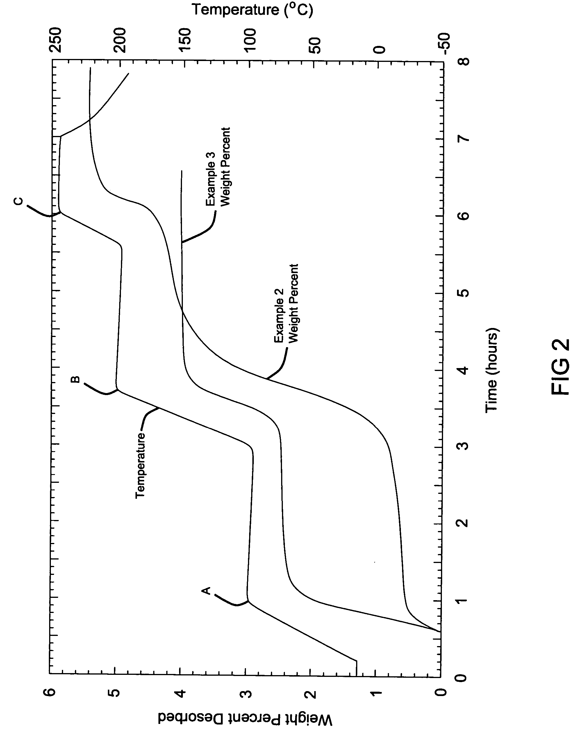
[0066] The hydrogen storage material system is the same as that in Example 1. Equal molar ratios of lithium hydroxide (LiOH) and lithium hydride (LiH) with measured amounts of 0.249 g LiH and 0.749 g of LiOH were mixed together and mechanically milled using the same ball milling techniques as described in Example 1, except that the mixture was milled for a shorter duration of 12 minutes.

example 3

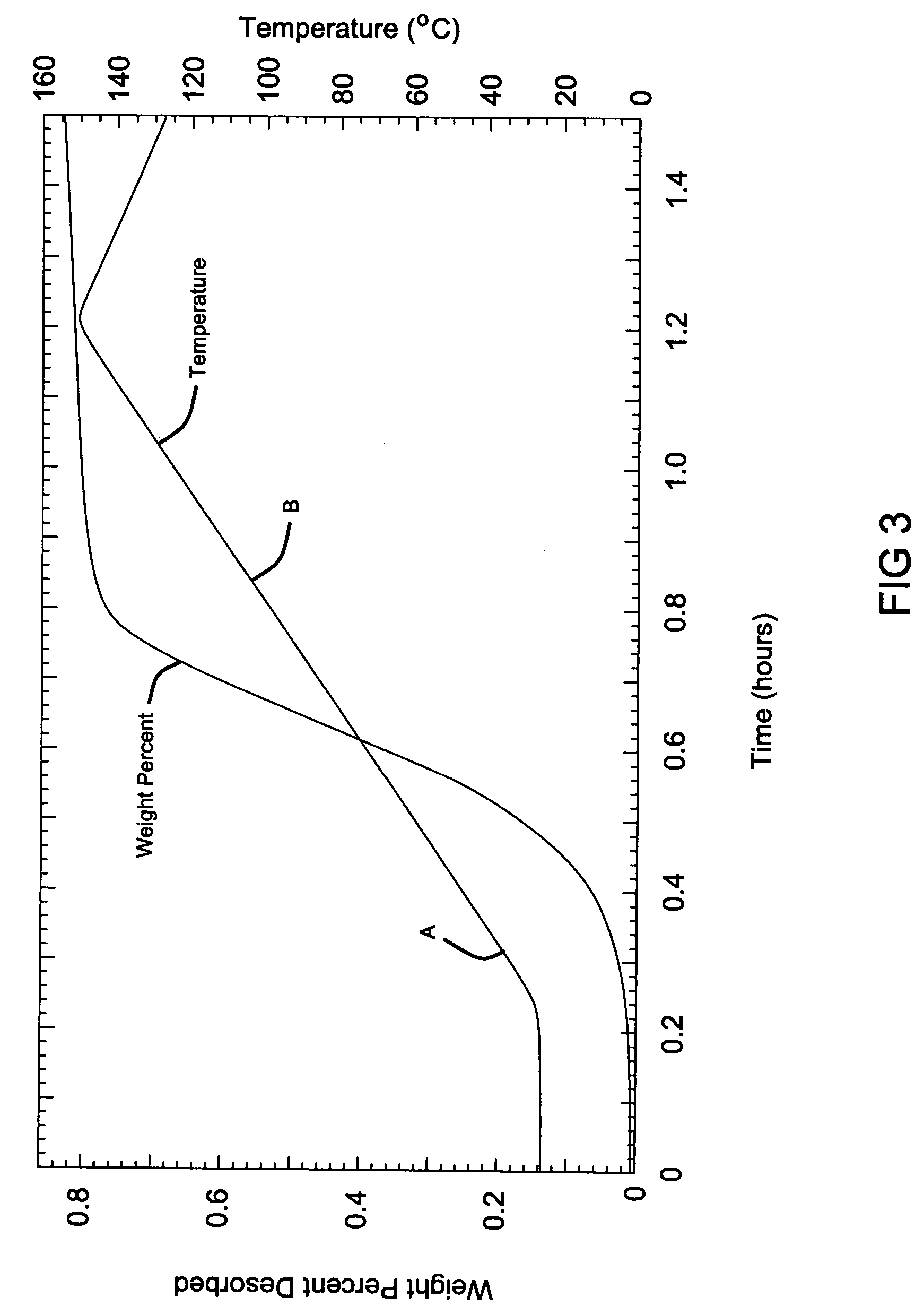
[0067] A hydrogen storage material system where the hydride is lithium hydride (LiH) and the hydroxide is lithium hydroxide (LiOH), similar to Example 2 above, is reacted in the presence of a catalyst, titanium chloride, TiCl3. A mixture of an equal molar ratio of lithium hydride (LiH) and lithium hydroxide (LiOH) weighed as 0.201 g LiH and 0.611 g of LiOH were mixed with one another. The catalyst was further added during milling at 10 mol % weighed at 0.385 TiCl3, and the entire mixture was then milled for 12 minutes.

[0068] The resulting samples from Examples 2 and 3 were subjected to a modified Sievert's analysis, where heat was applied in increasing steps. The first heating step reached a temperature of 100° C. (point A), the second step ramps up to 200° C. (point B) and then the final step reached 250° C. (point C). As can be observed from the data, the hydrogen generation began at approximately 80° C. for the Sample from Example 2 without a catalyst. As the temperature was hel...


PUM


Abstract

In one aspect, the present invention provides a system for methods of producing and releasing hydrogen from hydrogen storage compositions having a hydrogenated state and a dehydrogenated state. In the hydrogenated state, such a composition comprises a hydride and a hydroxide. In a dehydrogenated state, the composition comprises an oxide. A first reaction is conducted between a portion of the hydride and water to generate heat sufficient to cause a second hydrogen production reaction between a remaining portion of the hydride and the hydroxide.

Description

FIELD OF THE INVENTION [0001] The present invention relates to hydrogen storage compositions, the method of making such hydrogen storage compositions and use thereof. BACKGROUND OF THE INVENTION [0002] Hydrogen is desirable as a source of energy because it reacts cleanly with air producing water as a by-product. In order to enhance the desirability of hydrogen as a fuel source, particularly for mobile applications, it is desirable to increase the available energy content per unit volume and per unit mass of storage. Presently, this is done by conventional means such as storage under high pressure, at thousands of pounds per square inch (e.g., 5,000 to 10,000 psi), cooling to a liquid state, or absorbing into a solid such as a metal hydride. Pressurization and liquification require relatively expensive processing and storage equipment. [0003] Storing hydrogen in a solid material such as metal hydrides, provides volumetric hydrogen density which is relatively high and compact as a sto...

Claims


Application Information

Patent Timeline
IPC IPC(8): C01B3/06C01B3/08
CPCC01B3/065Y02E60/362Y02E60/324Y02E60/36Y02E60/32
Inventor MERTENS, FLORIAN O.JORGENSEN, SCOTT W.VAJO, JOHN J.
Owner GM GLOBAL TECH OPERATIONS LLC
Why Eureka
Try Eureka