Pyrolysis-based fuel processing method and apparatus

a fuel processing method and fuel technology, applied in the direction of combustible gas production, hydrogen separation using solid contact, climate sustainability, etc., can solve the problems of not being widely used in methanol, not readily available in most vehicles, and raising concerns about passengers' safety

Inactive Publication Date: 2005-09-01
WOJTOWICZ MAREK A +3
View PDF3 Cites 4 Cited by
  • Summary
  • Abstract
  • Description
  • Claims
  • Application Information

AI Technical Summary

Problems solved by technology

Fuel cells which are currently of commercial interest operate on streams of pure or nearly pure hydrogen, which is not readily available in most vehicles.
In this bus, compressed hydrogen is used to fuel the cells, which has raised concerns about passengers' safety.
The fact that methanol is not currently a widely used fuel poses obvious limitations.
There are also concerns related to long-term viability as well as corrosiveness and toxicity of methanol.
However, partial oxidation produces relatively small amounts of gaseous hydrogen, which is diluted with nitrogen, large amounts of carbon oxides and soot, and the efficiency of fuel utilization is relatively low.
Steam reforming is a well-established large scale technology, but design, construction, and operation of compact reformers is quite a challenge.
The use of heavier feedstocks, such as naphtha, is difficult, and this problem can be only partly alleviated by the use of specially prepared catalysts (Austin, G. T., Shreve's Chemical Process Industries, Fifth edition, McGraw-Hill, New York, 1984).
The advantages of ATR include compactness, and nitrogen dilution is the main disadvantage.

Method used


Image

  • Pyrolysis-based fuel processing method and apparatus
  • Pyrolysis-based fuel processing method and apparatus
  • Pyrolysis-based fuel processing method and apparatus

Examples


Embodiment Construction

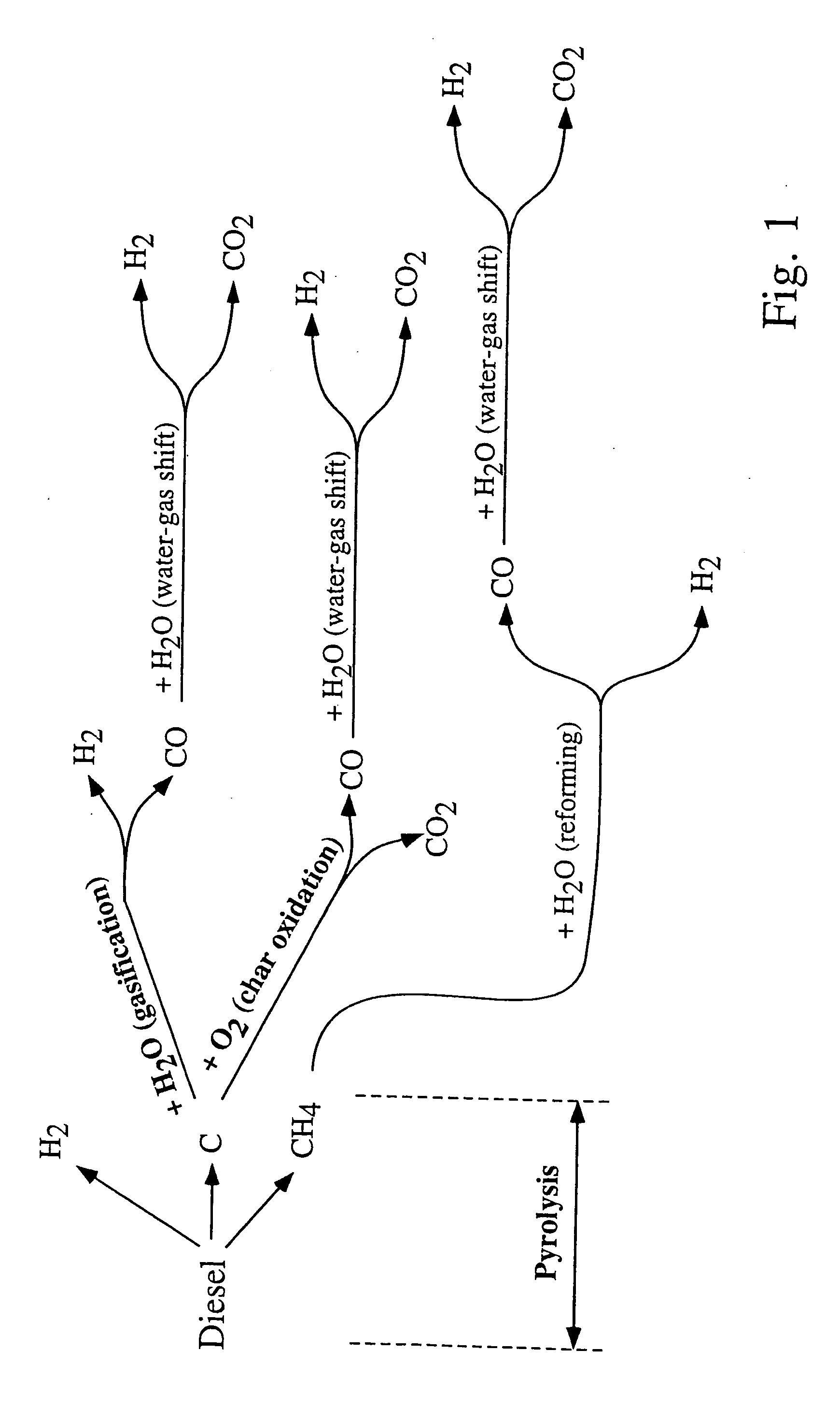
[0026] The fuel-conversion process is divided into several phases that preferably take place in the same reactor. The reactor mass, including packing (which will preferably comprise a catalyst bed), is used as a heat-transfer medium in such a way that the heat required by endothermic reactions is provided from preceding exothermic cycles. Thus, the reactor mass, which may comprise the reactor walls, catalyst bed, refractory liners, any suitable packing that increases the thermal capacity of the system, etc., constitutes the means for absorption and release of heat. The operation of the fuel processor is described in steps a-d below. FIG. 1 provides an overview of reaction pathways. [0027] At a cold start (not included in FIG. 1), the fuel is burned with air within the reactor volume until the maximum temperature of the reactor mass Tmax. is reached. The exhaust gases from this cycle are discarded. As an alternative, a rapid start-up could be achieved by the initial heating of the re...


PUM

PropertyMeasurementUnit
temperatureaaaaaaaaaa

Abstract

The method for generating a hydrogen-rich stream from hydrocarbon fuels, ultimately to produce hydrogen gas, involves the following two steps performed in a cyclic fashion: (1) pyrolysis of the hydrocarbon fuel to obtain a carbon-rich fraction and a hydrogen-rich fraction; and (2) oxidation of the carbon-rich fraction, or a portion of it, for heat generation. The method involves the following optional steps: (3) steam gasification of part of the carbon-rich fraction to produce additional amounts of hydrogen and carbon monoxide; (4) water-gas shift reaction to convert carbon monoxide to carbon dioxide with the simultaneous formation of additional amounts of hydrogen; and (5) steam reforming of light hydrocarbons that may be produced in step (1) to produce more hydrogen and carbon monoxide.

Description

CROSS-REFERENCE TO RELATED APPLICATION [0001] This application claims the benefit of U.S. Provisional Application No. 60 / 216,888, filed Jul. 7, 2000, in the names of the inventors designated herein and bearing the same title.STATEMENT REGARDING GOVERNMENT INTEREST [0002] The United States Government has rights in this invention under National Science Foundation grant No. DMI-9632781.BACKGROUND OF THE INVENTION [0003] Fuel cells which are currently of commercial interest operate on streams of pure or nearly pure hydrogen, which is not readily available in most vehicles. Neither is a source of pure hydrogen convenient or safe to carry on board commercial trucks, buses or other vehicles. However, liquid hydrocarbons, such as diesel fuels, are easily available and their handling, storage and distribution are well developed. Consequently, the large-scale use of fuel cells is expected to require conversion of liquid fuels into a stream of pure hydrogen or hydrogen / CO2 mixtures, with only ...

Claims


Application Information

Patent Timeline
Patent Type & Authority Applications(United States)
IPC IPC(8): C01B3/22C01B3/38C01B3/48C01B3/58C10J3/62H01M8/04H01M8/06
CPCB60L11/1894Y02T90/34B60L2200/36B60L2240/545C01B3/22C01B3/38C01B3/48C01B3/583C01B2203/0233C01B2203/0266C01B2203/0283C01B2203/044C01B2203/045C01B2203/047C01B2203/0495C01B2203/066C01B2203/0811C01B2203/0816C01B2203/0866C01B2203/1241C01B2203/1247C01B2203/127C01B2203/142C01B2203/1604C01B2203/1652C01B2203/1676C01B2203/169C01B2203/82C10J3/62H01M8/04022H01M8/0618H01M8/0668H01M8/0675H01M2250/20Y02T90/32C10J2200/06C10K1/004C10K3/006C10K3/04C10J2300/1646Y02E60/50B60L11/1898B60L50/72B60L58/34Y02T90/40
Inventor WOJTOWICZ, MAREK A.SERIO, MICHAEL A.KROO, ERIKSUUBERG, ERIC M.
Owner WOJTOWICZ MAREK A
Why Eureka
Try Eureka