Radon mitigation heater pipe

a heater pipe and radon technology, applied in the field of radon mitigation heater pipes, can solve the problems of reducing the service life of the heater pipe, and reducing the risk so as to reduce the risk of radon entering and accumulating inside the structure, and the effect of reducing the risk of failur

Inactive Publication Date: 2005-09-01
DOYLE MICHAEL J
View PDF28 Cites 11 Cited by
  • Summary
  • Abstract
  • Description
  • Claims
  • Application Information

AI Technical Summary

Benefits of technology

[0013] The present invention provides a simple, low-maintenance device for actively drawing radon-contaminated air from beneath the foundation of a structure, thus mitigating the risk that radon will enter into and accumulate inside of the structure. By using an internally heated section of duct to create a convective flow of air upward from the gas permeable sub-slab layer, expelling the radon-contaminated air above the roof of the structure, the device of the present invention eliminates the need for a fan. Therefo...

Problems solved by technology

A radon problem can exist in any home, regardless whether the home is new, old, well sealed, or drafty, and may even occur in a home without a basement.
Like other environmental pollutants, there is some uncertainty about the magnitude of radon health risks.
Because this system usually does not have a fresh air input into the gas permeable layer below the slab, airflow is restricted.
The reliance of this method on a fan causes problems with noise and condensation building up on the inside of the pipe.
The condensation then drips down on the fan, increasing the noise.
Because of the mechanical nature of the fan, its life span is limited.
U.S. Pat. No. 6,524,182 [Kilburn, et al.] discloses a fan-driven system having a sump well inlet and a ...

Method used


Image

  • Radon mitigation heater pipe
  • Radon mitigation heater pipe
  • Radon mitigation heater pipe

Examples


Embodiment Construction

[0019] The following detailed description is of the best presently contemplated mode of carrying out the invention. The description is not intended in a limiting sense, and is made solely for the purpose of illustrating the general principles of the invention. The various features and advantages of the present invention may be more readily understood with reference to the following detailed description taken in conjunction with the accompanying drawings.

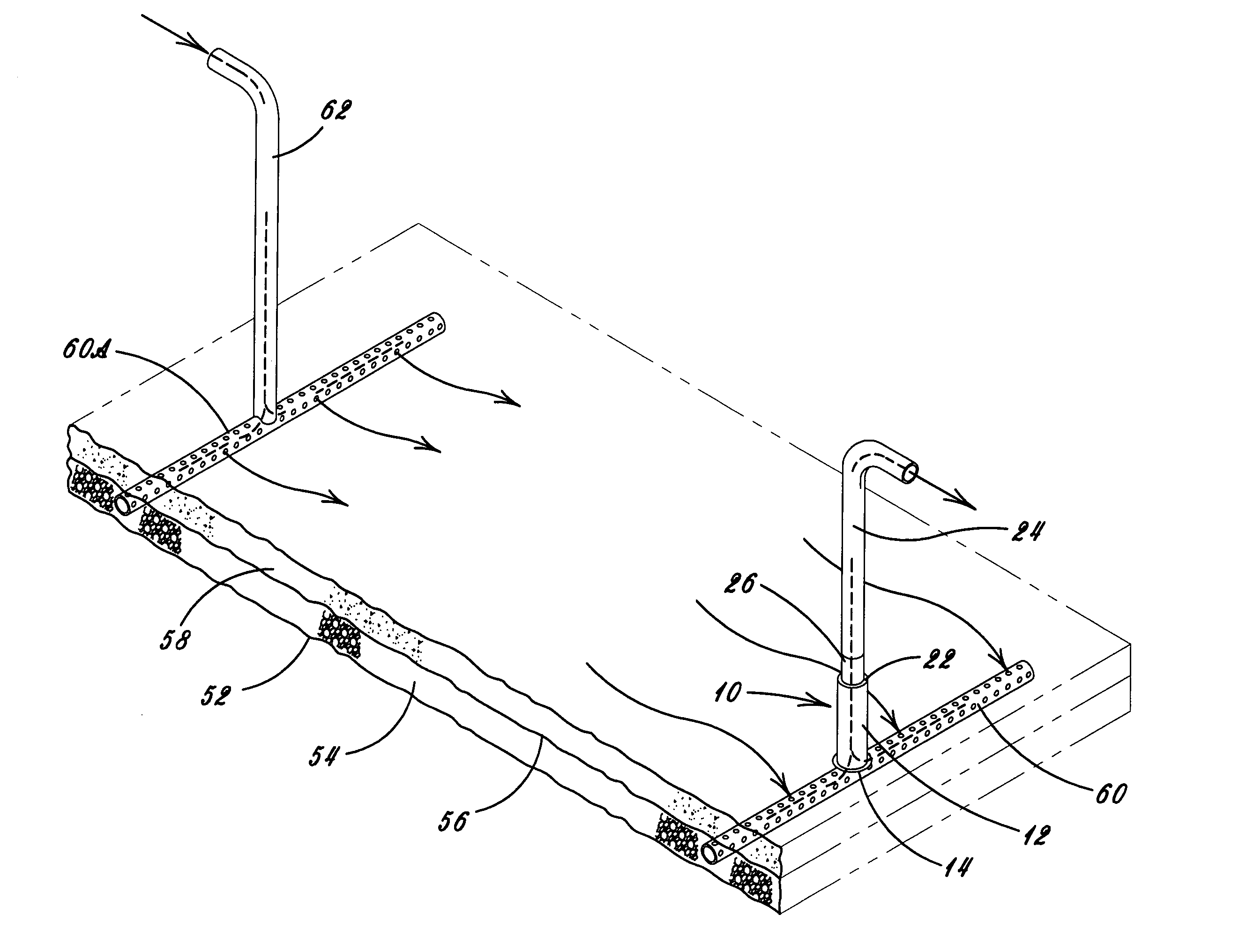
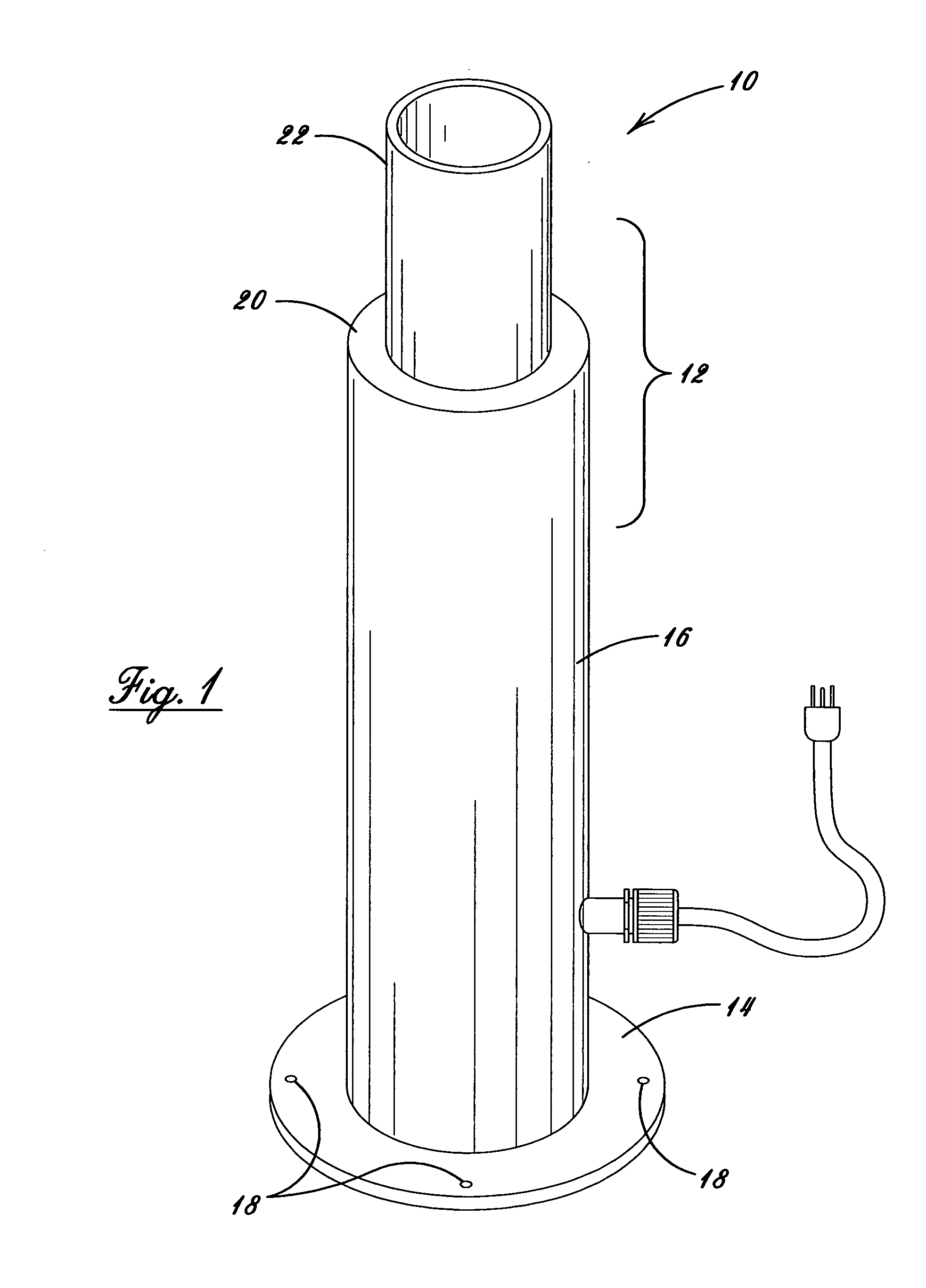
[0020] Referring now to the drawings in detail, where like numerals refer to like parts or elements, there is shown in FIG. 1 an exterior view of the radon mitigation device 10. The device is comprised of an external shell portion 12 and an internal heating portion 31.

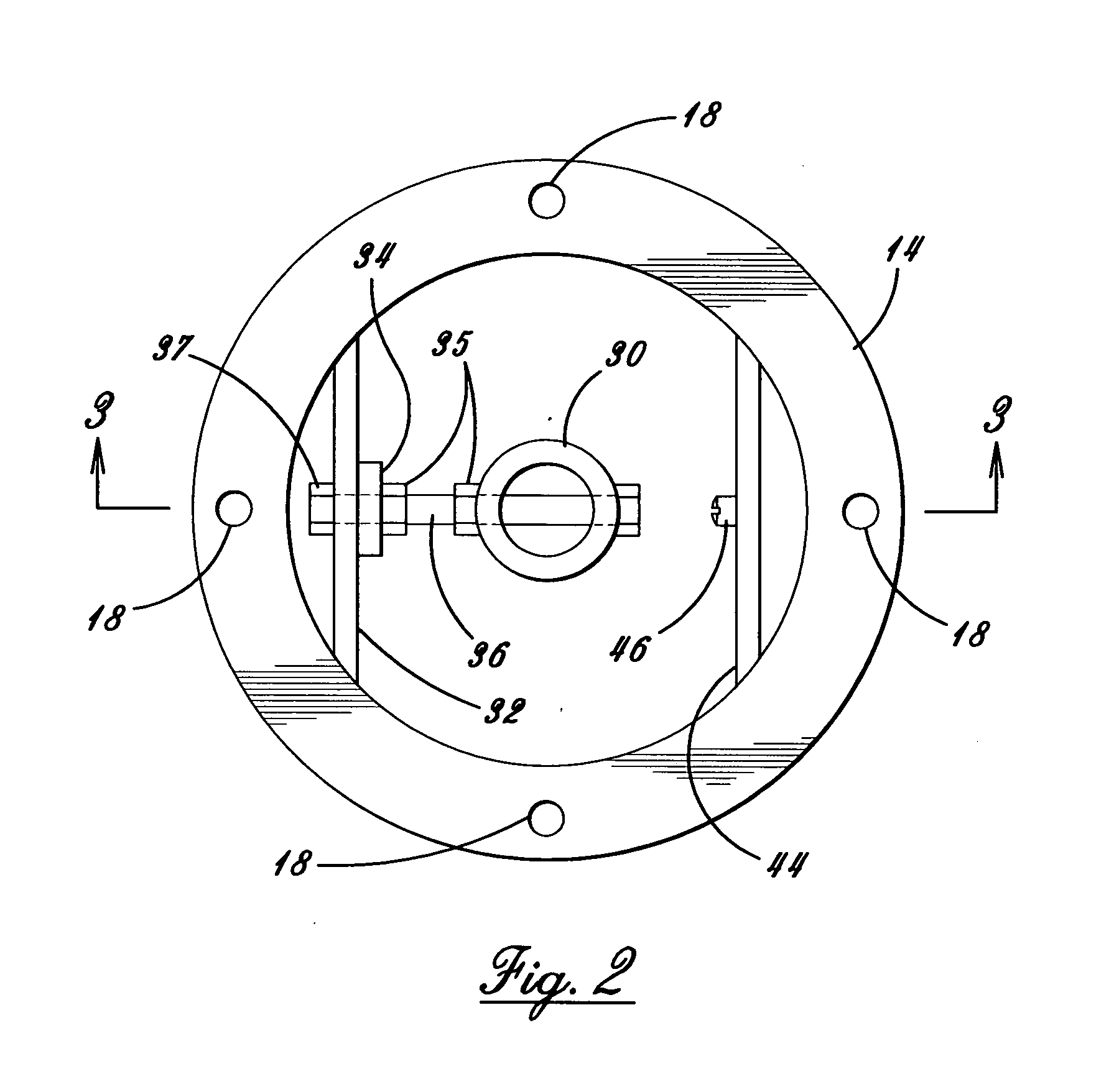
[0021] The external shell portion 12 is fabricated by welding several components together; however a one-piece metal casting would be a preferable construction technique for a mass produced device. The base 14 is made from a round flat plate or flange having a central...


PUM


Abstract

An apparatus and method for radon mitigation using natural convection to remove radon-contaminated air from beneath the slab foundation of a structure, building, or dwelling, comprising a section of vertically mounted convection duct including an internal heat source, an inlet duct extending from said convection duct through the slab into the gas permeable sub-slab layer, an outlet duct extending from said convection duct through the structure and out the roof thereof, the internal heat source comprising a thermally conductive tube disposed concentrically within said convection duct and heated by one or more electrical heater elements to assist the upward airflow of the radon-contaminated air from the structure.

Description

CROSS-REFERENCE TO RELATED APPLICATIONS [0001] This application is a continuation-in-part of U.S. patent application Ser. No. 10 / 773,076 filed on Feb. 5, 2004, which claims priority from U.S. Provisional Patent Application Ser. No. 60 / 445,135, filed on Feb. 5, 2003.BACKGROUND OF THE INVENTION [0002] The present invention relates generally to devices for radon mitigation in homes and other structures. More specifically, the present invention relates to an improved system for ventilating the foundation of a structure to remove radon gas so that it does not accumulate inside the structure. [0003] Radon is a radioactive gas generated by the natural (radioactive) decay of the uranium that is found in nearly all soils, and can be found all over the United States. The breakdown of uranium in soil, rock and water releases radon into the air we breathe. Radon can get into any type of building—homes, offices, and schools—and cause an elevated indoor radon level. It typically moves up through ...

Claims


Application Information

Patent Timeline
IPC IPC(8): F24F7/007H05B3/02
CPCE02D31/008F24F2007/004F24F2003/1696F24F11/0001F24F8/70
Inventor DOYLE, MICHAEL J.
Owner DOYLE MICHAEL J
Why Eureka
Try Eureka