Methods and devices for placing a conduit in fluid communication with a target vessel and a source of blood

a technology of target vessels and conduits, which is applied in the direction of prosthesis, surgical staples, therapy, etc., can solve the problems of increasing the risk of stroke, affecting the survival rate of patients, and affecting the safety of patients, so as to reduce stroke risk and overall patient morbidity, and the length is shorter

Inactive Publication Date: 2005-09-01
CARSON DEAN F +8
View PDF8 Cites 85 Cited by
  • Summary
  • Abstract
  • Description
  • Claims
  • Application Information

AI Technical Summary

Benefits of technology

[0014] Revascularization of the heart may be performed via a ventricular bypass procedure carried out according to one embodiment of the invention. This procedure provides several benefits. For example, no aortic manipulation is necessary because a heart chamber is the blood source. Obviating the need to manipulate the aorta significantly reduces stroke risk as well as overall patient morbidity. Also, if an autologous vessel is used to form a conduit for the ventricular bypass procedure, a shorter length is needed than in conventional CABG procedures. This is because the distance between the coronary vessel and the heart chamber is considerably less than the distance between the coronary vessel and the aorta. As a result, a given length of autologous tissue will provide more bypass conduits suitable for use in a ventricular bypass procedure carried out according to the invention.

Problems solved by technology

Despite the considerable advances that have been realized in cardiology and cardiovascular surgery, heart disease remains the leading cause of death throughout much of the world.
Clamping or otherwise manipulating the aorta places the patient at risk in some cases due to the likelihood that such manipulation will release embolic material into the bloodstream.
A drawback associated with CABG and some ventricular bypass procedures is the harvesting of autologous vessels for use as bypass grafts.
Although such synthetic grafts have been somewhat effective when used to treat peripheral vessels, they have not been successful in treating small diameter vessels, such as coronary arteries.
A particularly challenging task that must be performed during CABG procedures, as well as proposed ventricular bypass procedures, is attaching the conduit to the target vessel, particularly when the attachment is performed via a handsewn, sutured anastomosis.
Sewing the conduit to the target vessel is a very technical and time-consuming procedure given the diameter of the conduit and the coronary artery, typically from 1 mm to 4 mm.
The difficulty in forming the sutured anastomosis is exacerbated when access to the target vessel is restricted or limited, as is the case in a minimally invasive or percutaneous procedure.
While those in the art have proposed various anastomotic couplings intended to replace a sutured anastomosis, none has performed well enough to receive any level of acceptance in the field.
Many of the proposed couplings penetrate or damage the target vessel wall, fail to produce a fluid-tight seal between the conduit and vessel, or are simply cumbersome and difficult to deliver or deploy.

Method used


Image

  • Methods and devices for placing a conduit in fluid communication with a target vessel and a source of blood
  • Methods and devices for placing a conduit in fluid communication with a target vessel and a source of blood
  • Methods and devices for placing a conduit in fluid communication with a target vessel and a source of blood

Examples


Embodiment Construction

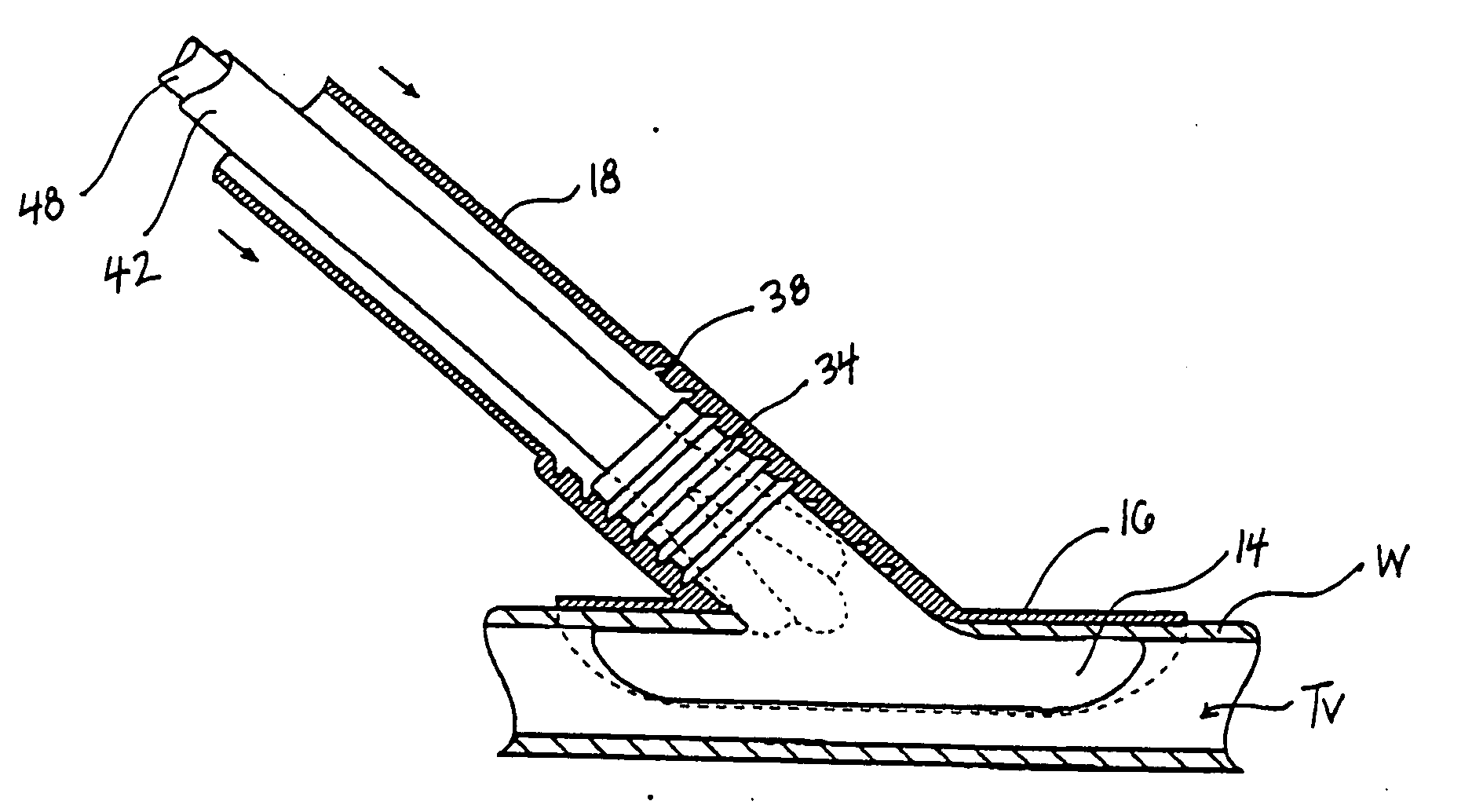
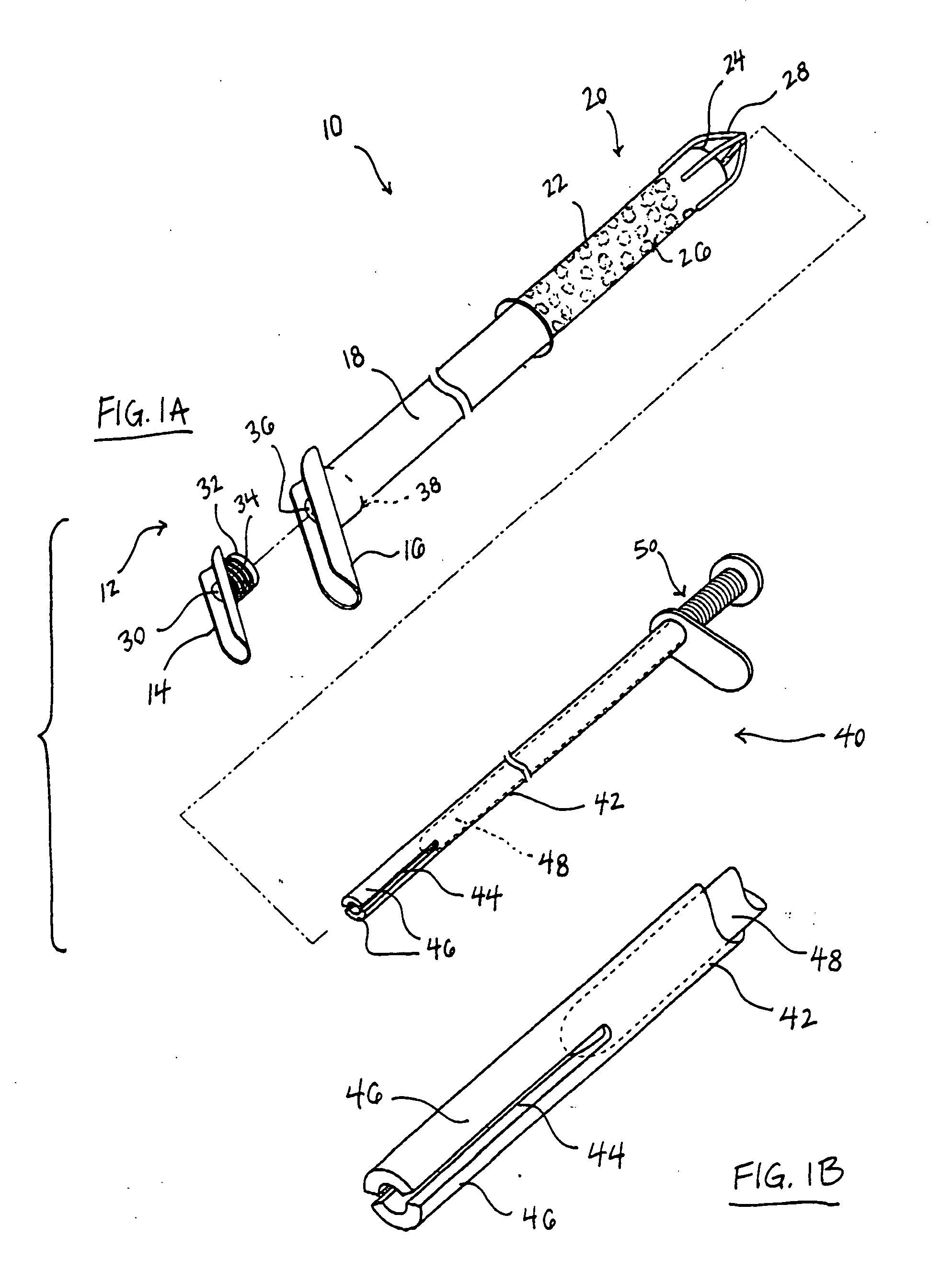
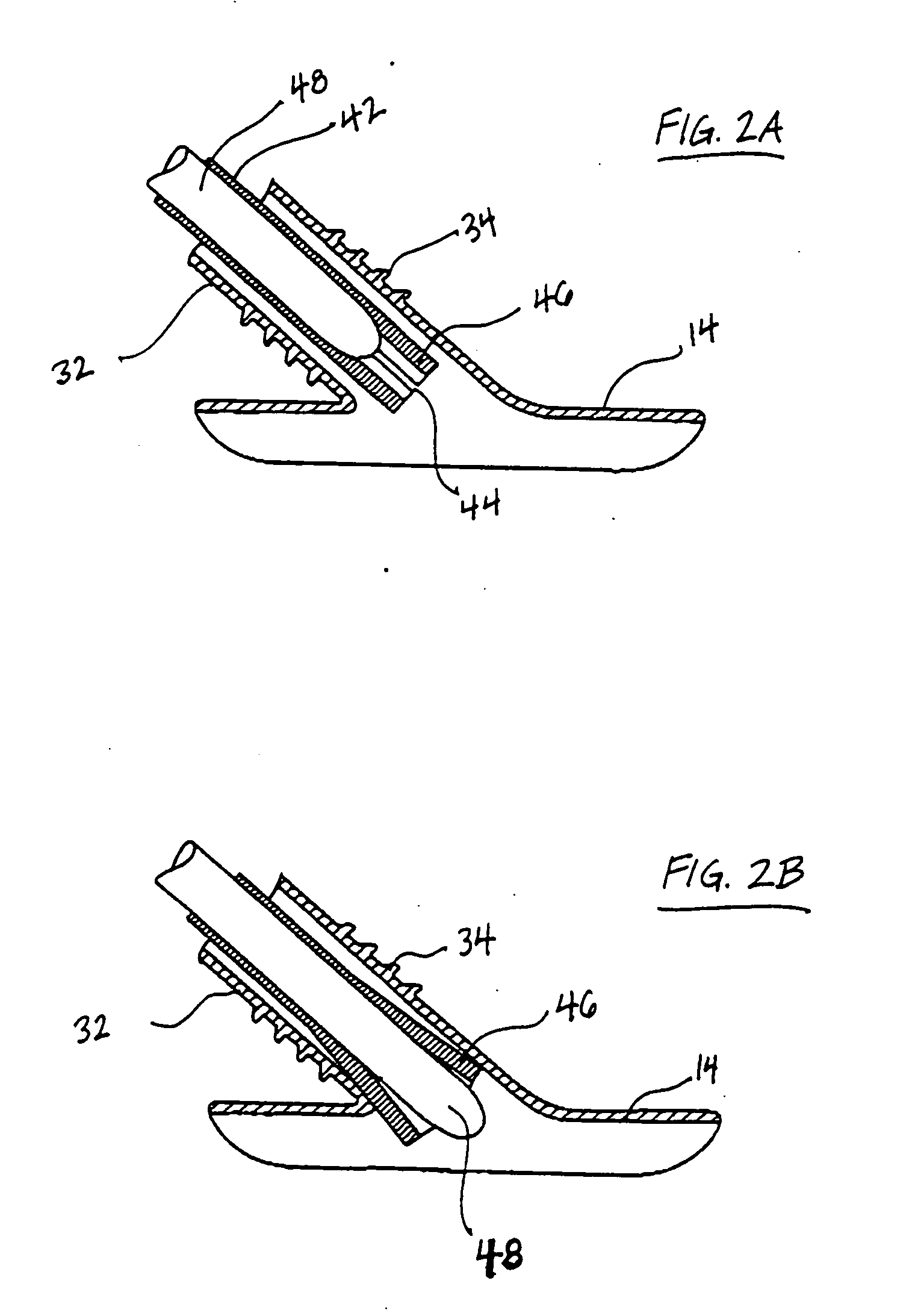
[0062] The present invention relates to methods and devices for securing a conduit to a target vessel, as well as methods and devices for placing the conduit in fluid communication with a source of blood. Various conduit configurations, anastomotic couplings for securing the conduit to the target vessel or the blood source, and methods for establishing one ore more flow paths between the blood source and the target vessel are disclosed as well.

[0063] In a preferred embodiment, the conduit is coupled to a source of blood, for example, a heart chamber containing oxygenated blood, and a target vessel, for example, a coronary vessel (e.g., artery or vein). It will be recognized, however, that the invention may be used to form a blood flow path between any other luminal structures, some examples of which are set forth below. As used herein, luminal structure means any anatomical structure, natural or synthetic, that is hollow and defines a lumen, for example, a blood vessel or tubular o...


PUM


Abstract

Devices and methods for placing a conduit in fluid communication with a target vessel to communicate the target vessel with a source of blood. A conduit is coupled to the target vessel by first and second securing components that compress or sandwich the vessel wall. The conduit may be preshaped to assume a desired orientation when in an unbiased state, for example, to allow the conduit to be deformed during delivery and then regain its desired orientation once which is regained when deployed. The first and second securing components may be any shape but are preferably elongated in the direction of the vessel axis, e.g., elliptical or rectangular, such that a minimum amount of material is present at the outlet to closely approximate the cross-sectional area of the native target vessel. The securing components do not significantly occlude the target vessel lumen, may be secured to the vessel wall in non-penetrating fashion, and provides a fluid-tight seal around the attachment site. The conduit may comprise tissue, synthetic material, etc., and one or both securing components may be constructed or provided with means for attaching an autologous vessel.

Description

CROSS-REFERENCE TO RELATED APPLICATIONS [0001] This application is a continuation-in-part of application Ser. No. 09 / 393130, filed on Sep. 10, 1999 and entitled “Anastomotic Methods and Devices For Placing a Target Vessel in Fluid Communication with a Source of Blood,” which is a continuation-in-part of application Ser. No. 09 / 232,103, filed on Jan. 15, 1999 and entitled “Methods and Devices for Forming Vascular Anastomoses,” and application Ser. No. 09 / 232,062, filed on Jan. 15, 1999 and entitled “Methods and Devices For Bypassing an Obstructed Target Vessel by Placing the Vessel in Communication with a Heart Chamber Containing Blood.” This application is also a continuation-in-part of application Ser. No. 09 / 023,492, filed on Feb. 13, 1998 and entitled “Methods and Devices Providing Transmyocardial Blood Flow to the Arterial Vascular System of the Heart.” The entire subject matter of each of these parent applications is incorporated herein by reference.BACKGROUND OF THE INVENTION ...

Claims


Application Information

Patent Timeline
Patent Type & Authority Applications(United States)
IPC IPC(8): A61B17/00A61B17/04A61B17/064A61B17/11A61B17/12A61B19/00A61F2/02A61F2/06A61F2/24
CPCA61B17/04A61B17/0643A61B17/11A61B19/54A61B2017/00243A61B2017/00247A61F2/2493A61B2017/1107A61B2017/1135A61B2018/00392A61F2/064A61F2/07A61B2017/00252A61B90/39
Inventor CARSON, DEAN F.REO, MICHAEL L.OLSON, STEPHEN L.LEPULU, KEKECREWS, SAM T.COLE, DAVID H.SHARKAWY, ADAMGITTINGS, DARIN C.FOLEY, MARK J.
Owner CARSON DEAN F
Why Eureka
Try Eureka