Engine system and method for efficient emission control device purging

Active Publication Date: 2005-09-08
FORD GLOBAL TECH LLC
View PDF26 Cites 9 Cited by
  • Summary
  • Abstract
  • Description
  • Claims
  • Application Information

AI Technical Summary

Benefits of technology

[0007] In this way, it is possible, in one embodiment, to provide the ability to operate some cylinders without fuel injection, and save still further fuel when it may be desired to purge NOx stored in a downstream emission control device. Note, however, that the above approach can be used in other situations as well to improve performance.
[0008] In another aspect, another disadvantage with prior approaches can relate to transitioning from operation with some cylinder deactivated and active cylinders combusting, to all cylinders combusting. Specifically, retarded ignition timing is used, along with throttling to reduce any torque disturbance that may result. However, throttle is generally to slow due to manifold filling effects, and as such, ignition timing retard is heavily relied upon. Significant reliance on ignition timing retard, however, can result is degraded fuel economy.
[0009] Therefore, to overcome the above disadvantage, the inventors herein have recognized that the above fuel economy degradation can be reduced by operating the re-enabled cylinders at a lean combustion limit, thereby reducing the amount of ignition timing retard that may be needed. In one example, a method for controlling an engine having at least a first and second group of cylinders comprises:

Problems solved by technology

The inventors herein have recognized that such an approach may result in wasting excess fuel in configurations where there are multiple cylinder banks, each having an upstream emission control device, when it is desired to reduce NOx stored in a downstream device.
In another aspect, another disadvantage with prior approaches can relate to transitioning from operation with some cylinder deactivated and active cylinders combusting, to all cylinders combusting.
However, throttle is generally to slow due to manifold filling effects, and as such, ignition timing retard is heavily relied upon.
Significant reliance on ignition timing retard, however, can result is degraded fuel economy.

Method used


Image

  • Engine system and method for efficient emission control device purging
  • Engine system and method for efficient emission control device purging
  • Engine system and method for efficient emission control device purging

Examples


Embodiment Construction

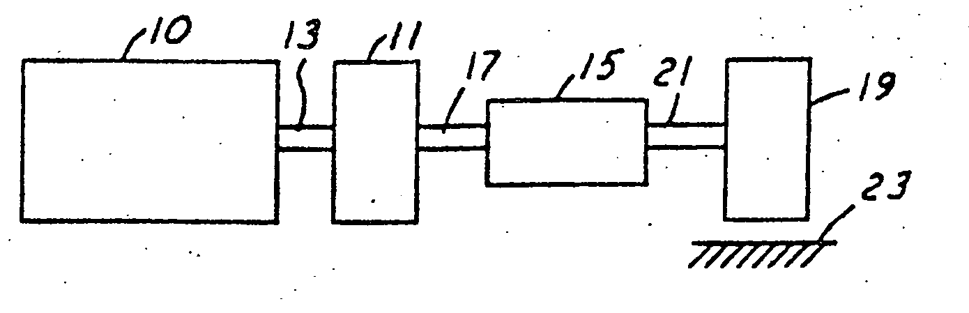
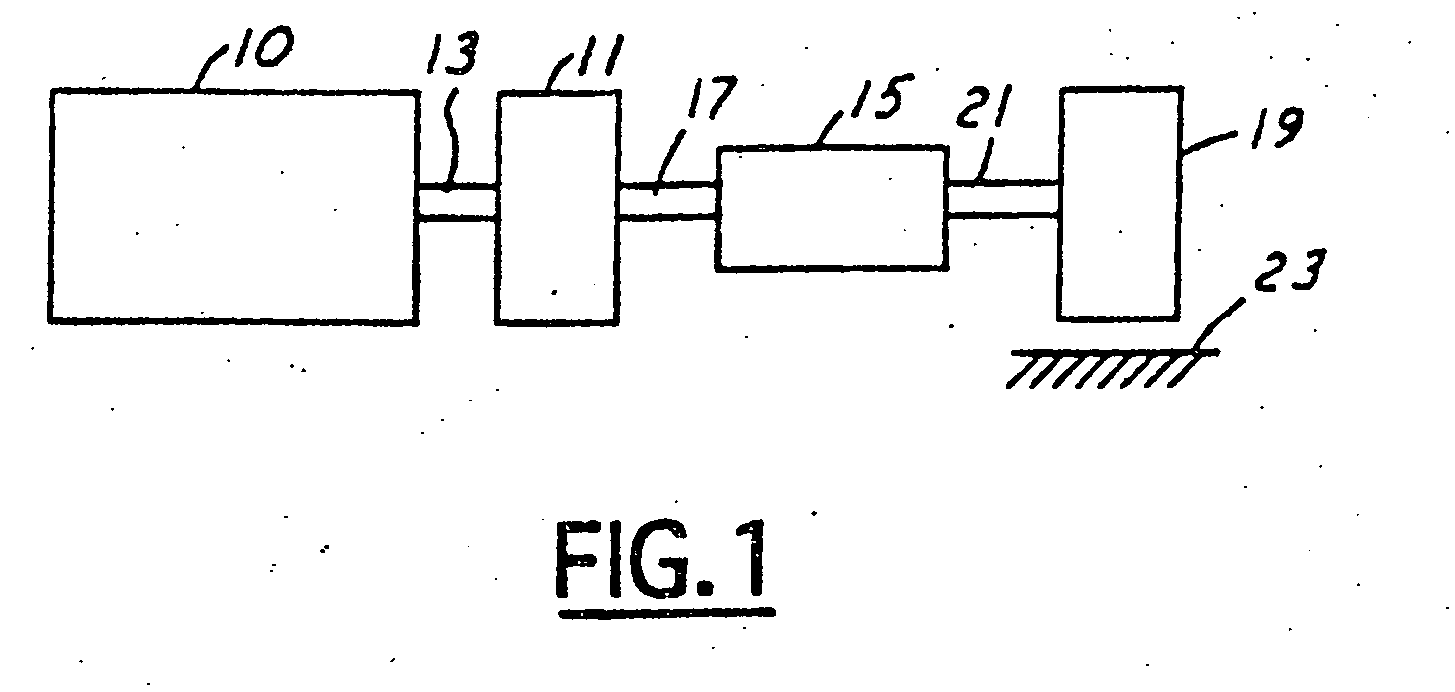
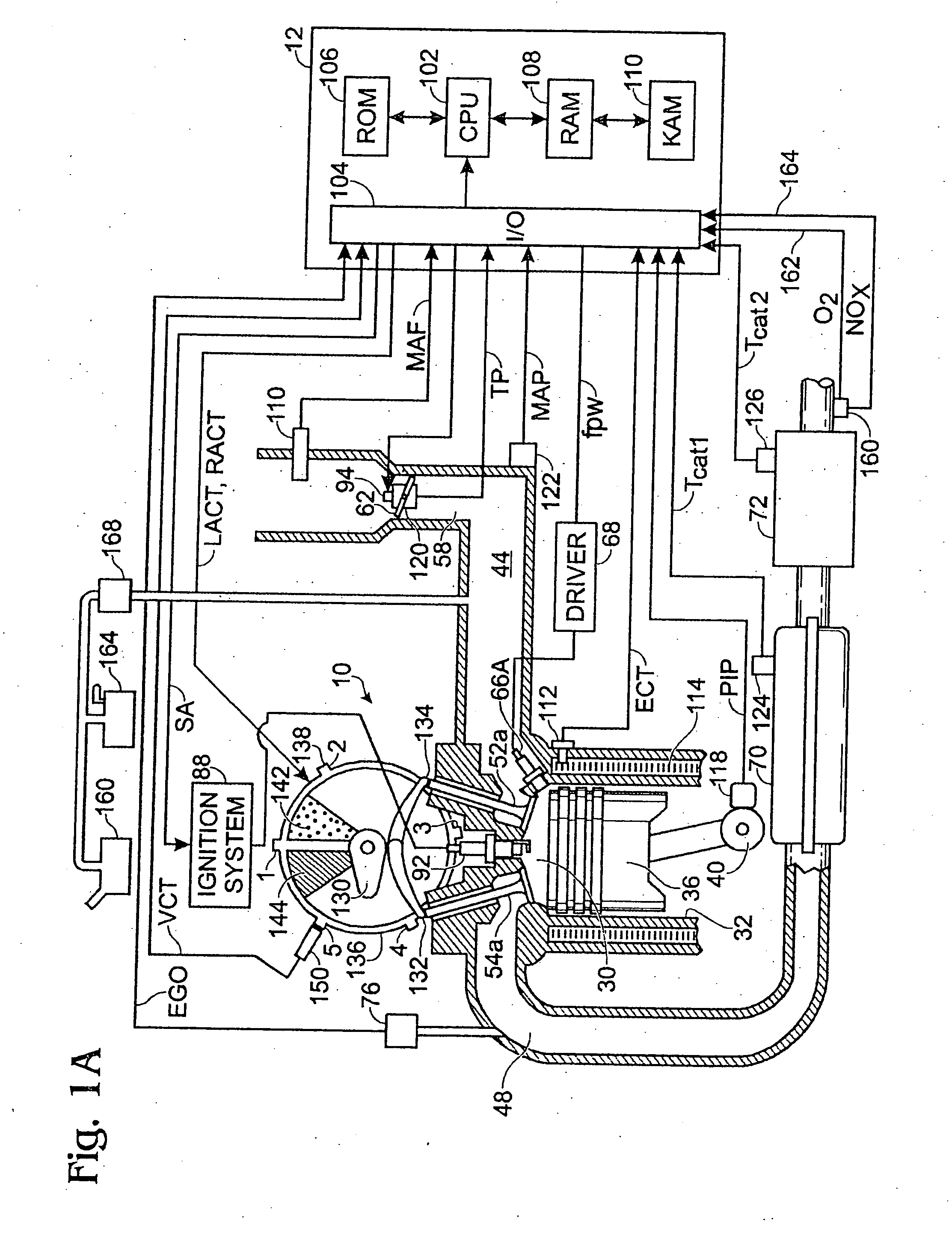
[0023] Referring to FIG. 1, internal combustion engine 10, further described herein with particular reference to FIGS. 1A and 1B, is shown coupled to torque converter 11 via crankshaft 13. Torque converter 11 is also coupled to transmission 15 via turbine shaft 17. Torque converter 11 has a bypass, or lock-up clutch 14 which can be engaged, disengaged, or partially engaged. When the clutch is either disengaged or partially engaged, the torque converter is said to be in an unlocked state. The lock-up clutch 14 can be actuated electrically, hydraulically, or electro-hydraulically, for example. The lock-up clutch 14 receives a control signal (not shown) from the controller, described in more detail below. The control signal may be a pulse width modulated signal to engage, partially engage, and disengage, the clutch based on engine, vehicle, and / or transmission operating conditions. Turbine shaft 17 is also known as transmission input shaft. Transmission 15 comprises an electronically c...


PUM


Abstract

Various systems and methods are disclosed for carrying out combustion in a fuel-cut operation in some or all of the engine cylinders of a vehicle. Further, various subsystems are considered, such as fuel vapor purging, air-fuel ratio control, engine torque control, catalyst design, and exhaust system design.

Description

BACKGROUND AND SUMMARY [0001] Engines are usually designed with the ability to deliver a peak output, although most engine operation is performed well below this peak value. As such, it can be beneficial to operate with some cylinders inducting air without fuel injection as described in U.S. Pat. No. 6,568,177. [0002] As described in U.S. Pat. No. 6,568,177, periodically it may be necessary to purge stored NOx by operating all of the cylinders stoichiometric or rich. [0003] The inventors herein have recognized that such an approach may result in wasting excess fuel in configurations where there are multiple cylinder banks, each having an upstream emission control device, when it is desired to reduce NOx stored in a downstream device. Specifically, fuel is must be used to reduce stored oxidants in both upstream devices, before downstream stored NOx can be reduced. [0004] The above disadvantage can be overcome by a method for controlling an engine having at least a first and second gr...

Claims


Application Information

Patent Timeline
IPC IPC(8): F01N3/00F02M7/00
CPCF02D41/0082F02D41/0087F02D41/0275F02D41/1408F02M25/0749Y02T10/47F01N3/0842F01N9/00F01N2430/02F01N2900/1614F02M7/00F02D17/02F02M26/43Y02T10/40
Inventor SURNILLA, GOPICHANDRAGORALSKI, CHRISTIAN T.SMITH, STEPHEN B.
Owner FORD GLOBAL TECH LLC
Why Eureka
Try Eureka