Thermal developing apparatus

a technology of developing apparatus and developing chamber, which is applied in the direction of recording apparatus, instruments, photosensitive materials, etc., can solve the problems of increasing the size of the apparatus, reducing the density of the apparatus, and fluctuating density, so as to reduce the installation space of the apparatus, simplify the driving mechanism, and reduce the effect of the installation spa

Inactive Publication Date: 2005-09-08
FUJIFILM CORP +1
View PDF5 Cites 13 Cited by
  • Summary
  • Abstract
  • Description
  • Claims
  • Application Information

AI Technical Summary

Benefits of technology

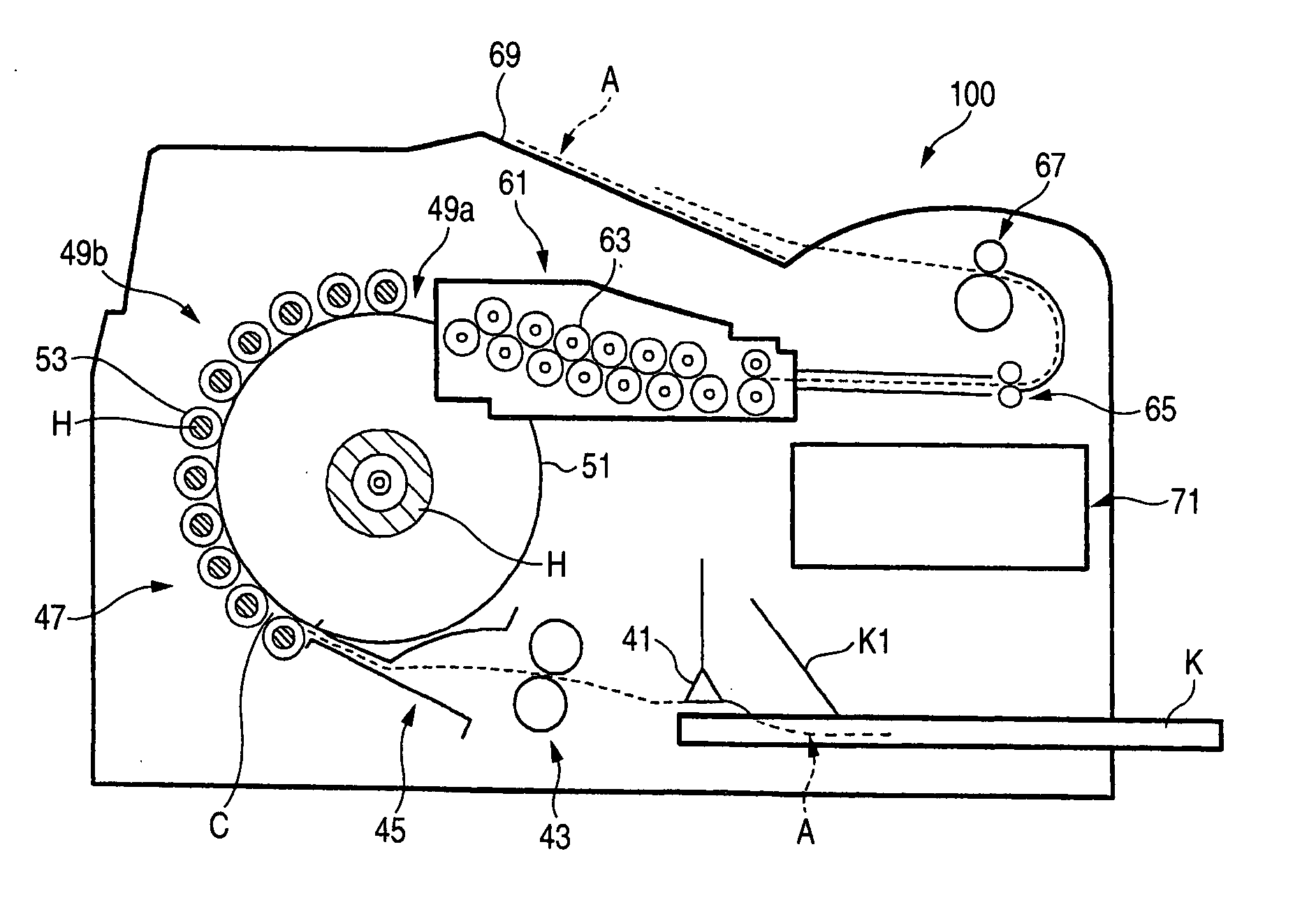
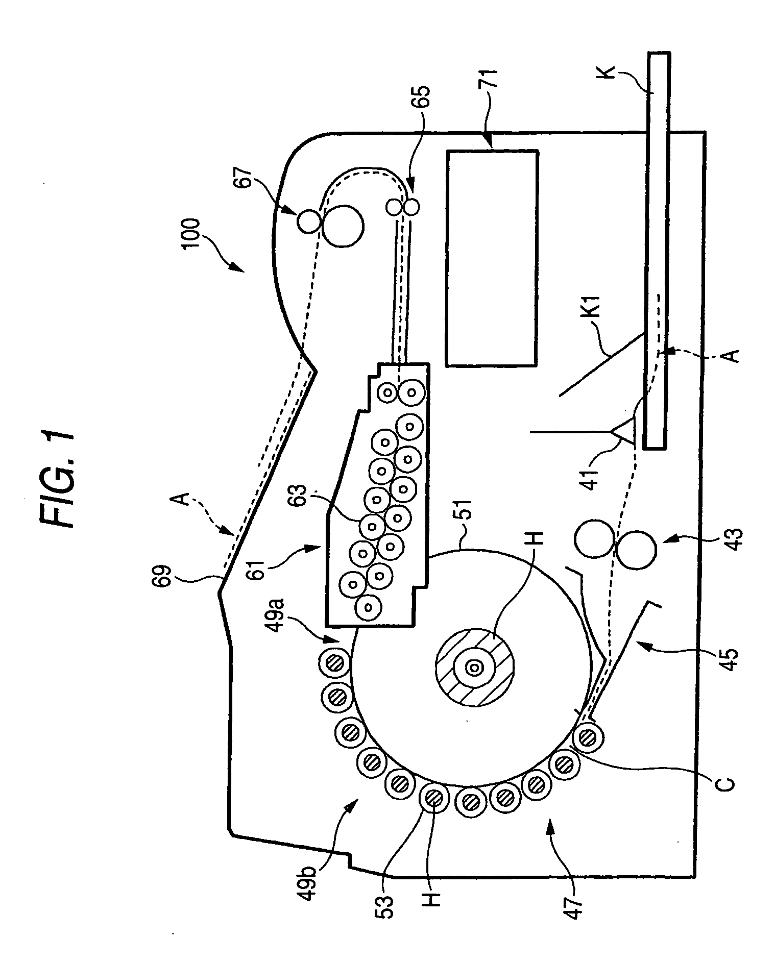
[0036] According to the invention, a cassette installing part of a thermal developing apparatus capable of attaining uniform thermal development on both surfaces is omitted but a manual feeding tray is used, and a large cylindrical drum in a thermal developing part is replaced by a compact heating and conveying unit arranged serially in the conveying direction, whereby the apparatus can be further miniaturized to reduce the installation space thereof.
[0037] It is also possible that the manual feeding tray can be made steeply slanted, and the apparatus is miniaturized and thus placed vertically or hung on a wall, whereby the installation space thereof can be further reduced.
[0038] In the compact heating and conveying unit, a timing belt is engaged with the driving pulleys of the respective conveying rollers to drive the plural conveying rollers constituting the guide surface of the conveying path, whereby the driving mechanism is simplified and miniaturized, and a recording material can be smoothly conveyed in the curved conveying path.

Problems solved by technology

Furthermore, in the case where heat is not sufficiently transmitted to the image forming layer on the side not heated, development thereof becomes insufficient to cause density fluctuation, in which the density thereof is reduced.
However, the thermal developing apparatus shown in FIG. 1 is of such a type that a cassette housing a double sided photosensitive film is inserted, and has a problem in increasing the size of the apparatus.

Method used


Image

  • Thermal developing apparatus
  • Thermal developing apparatus
  • Thermal developing apparatus

Examples


example

1. Preparation of PET Support And Undercoating

1-1. Film Formation

[0395] PET having an intrinsic viscosity IV of 0.66 (measured in phenol / tetrachloroethane (6 / 4 by volume) at 25° C.) was obtained by the ordinary method using terephthalic acid and ethylene glycol. PET was pelletized and then dried at 130° C. for 4 hours. PET was colored with a blue dye (1,4-bis(2,6-diethylanilinoanthraquinone)) and extruded from a T-die, followed by quenching, to obtain an unstretched film.

[0396] The unstretched film was stretched lengthwise in 3.3 times by using rolls having different peripheral speeds and then stretched crosswise in 4.5 times with a tenter. Thereafter, the film was thermally fixed at 240° C. for 20 seconds and then relaxed crosswise in 4% at the same temperature. The film was slitted at the chuck part of the tenter and subjected to knurling on both edges, followed by being wound at 4 kg / cm2, to obtain a roll of a film having a thickness of 175 μm.

1-2. Surface Corona Treatment...


PUM


Abstract

A thermal developing apparatus for visualizing a latent image recorded on a photosensitive thermal developing recording material by heating the photosensitive thermal developing recording material with heating unit while conveying the photosensitive thermal developing recording material with conveying unit along a conveying path having the heating unit equipped therewith, the thermal developing apparatus containing a manual feeding tray for manually feeding the exposed photosensitive thermal developing recording material into the thermal developing apparatus.

Description

[0001] This application is based on Japanese Patent application JP 2004-061246, filed Mar. 4, 2004, the entire content of which is hereby incorporated by reference. This claim for priority benefit is being filed concurrently with the filing of this application. BACKGROUND OF THE INVENTION [0002] 1. Field of the Invention [0003] The present invention relates to a thermal developing apparatus for heating a photosensitive thermal developing recording material to visualize a latent image recorded on an image forming layer of the photosensitive thermal developing recording material. [0004] 2. Description of the Related Art [0005] An image forming apparatus, referred to as a medical imager, for example, forms a print of a visible image from an image measured with a medical measuring instrument, such as CT and MRI. The image forming apparatus uses a photosensitive thermal developing recording material having a support, such as a PET film, having formed thereon an image forming layer having...

Claims


Application Information

Patent Timeline
Patent Type & Authority Applications(United States)
IPC IPC(8): B65H11/00G03D13/00G03C1/52G03G15/06
CPCG03G15/6597G03D13/002
Inventor DENAWA, TATSUYUKI
Owner FUJIFILM CORP
Why Eureka
Try Eureka