Heat dissipation structure

Inactive Publication Date: 2005-09-08
HSU HUL CHUN
View PDF5 Cites 17 Cited by
  • Summary
  • Abstract
  • Description
  • Claims
  • Application Information

AI Technical Summary

Benefits of technology

[0009] The present invention provides a heat dissipation structure which uses interlock between a thermal conductive base and a heat sink to increase contact intensity and reduce thermal resistance. Fur

Problems solved by technology

In the past, the operation speed of the computer central processing unit was so slow that installation of a heat dissipation fan along is sufficient to dissipate heat generated thereby.
However, the design of heat dissipation device is generally restricted by limited space within the computer.
As each of the heat pipes 20a is in the form of a thin elongate cylindrical tube, the space for installing wick structure and working fluid is very limited.
Therefo

Method used


Image

  • Heat dissipation structure
  • Heat dissipation structure
  • Heat dissipation structure

Examples


Embodiment Construction

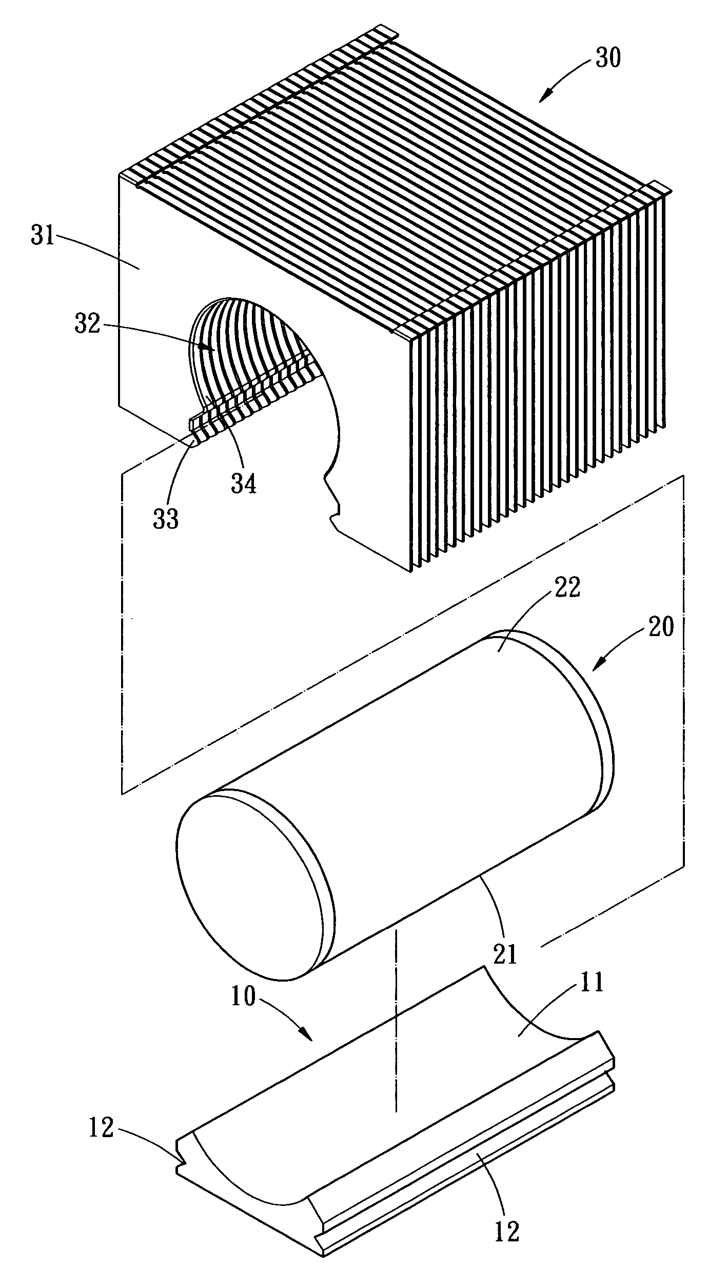
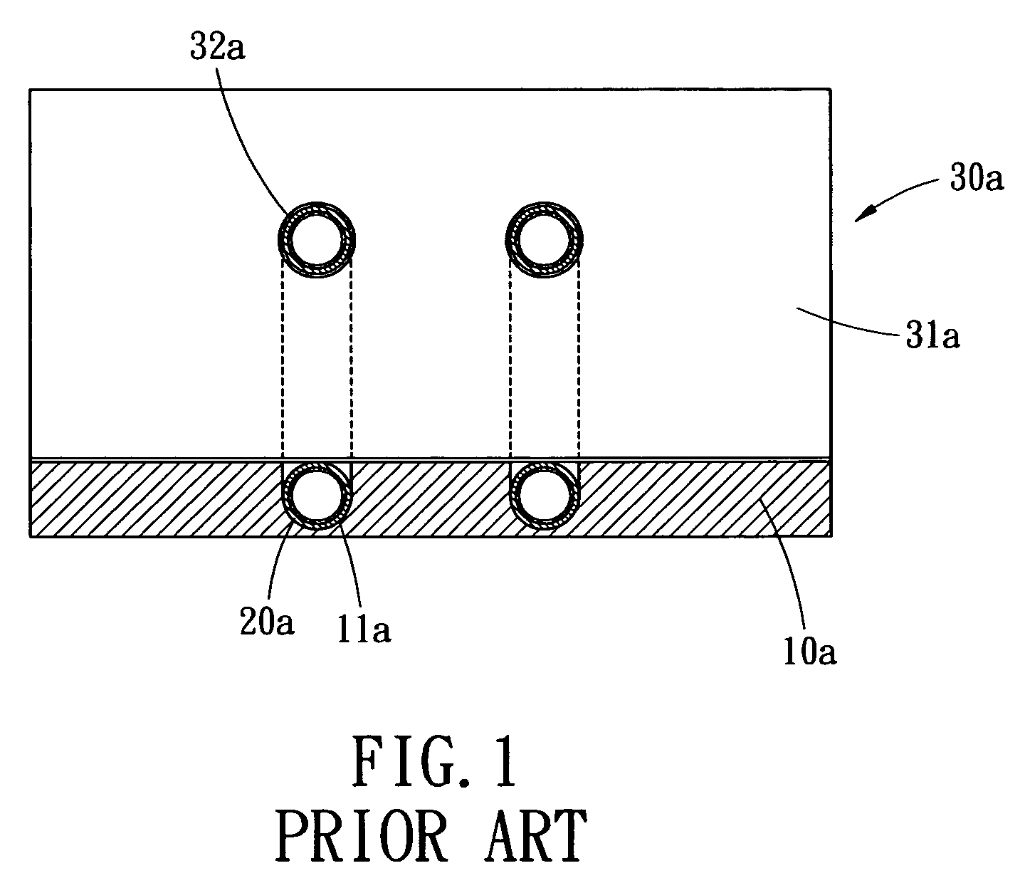
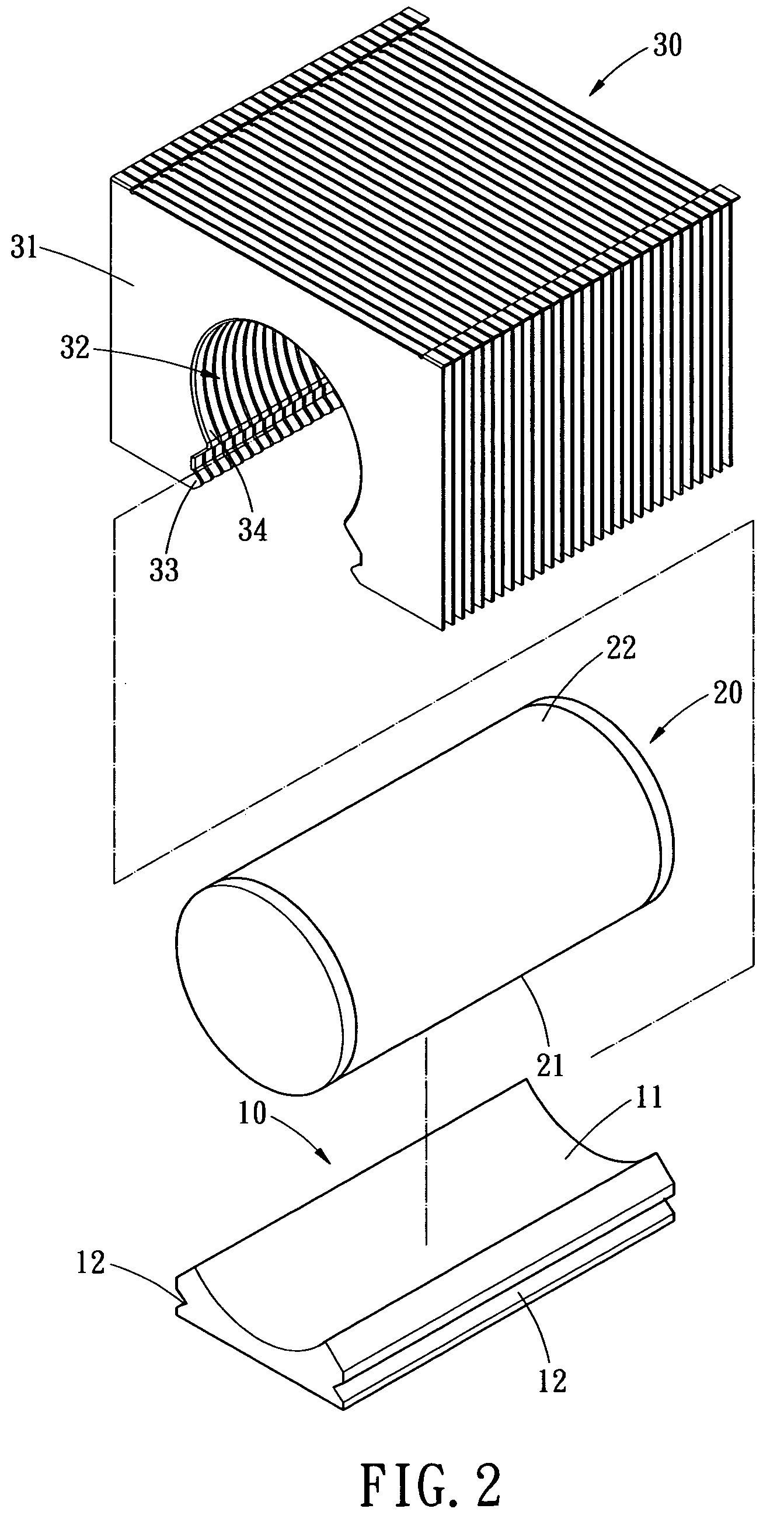
[0024] Referring now to the drawings wherein the showings are for purpose of illustrating preferred embodiments of the present invention only, and not for purposes of limiting the same. As shown in FIGS. 2 and 3, the present invention provides a heat dissipation structure including a thermal conductive base 10, a heat pipe 20 and a heat sink 30.

[0025] The thermal conductive base 10 is preferably fabricated from conductive material such as aluminum or copper, for example. The top surface of the thermal conductive base 10 is contoured with a curve-shape supporting part 11. The supporting part 11 is in the form of an open seat allowing thermal conductive paste such as tin paste to be uniformly coated thereon. Each side surface of the supporting part 11 includes a recessed groove or a protruding hook to serve as a first interlocking part 12. In this embodiment, a V-shape recessed groove is formed to serve as the first interlocking part 12.

[0026] The heat pipe 12 includes a cylindrical...


PUM


Abstract

A heat dissipation structure installed on a computer central processing unit or a heat generating device, has a thermal conductive base, at least one heat pipe and a heat sink. The thermal conductive base has a supporting part and a first interlocking part. The supporting part allows the heat pipe mounted thereon. The heat sink has a plurality of fins configured with a receiving slot and a second interlocking part. The second interlocking part is engaged with the first interlocking part, while the receiving slot and the supporting part of the thermal conductive base enclose the heat pipe therein to form the heat dissipation structure. By the connection between the thermal conductive pipe and the heat sink, the contact intensity between various devices is increased, such that the heat conduction performance is improved.

Description

BACKGROUND OF THE INVENTION [0001] The present invention relates in general to a heat dissipation structure, and more particularly, to a heat dissipation structure that improves heat conduction performance by increasing contact intensity between various elements. [0002] In the past, the operation speed of the computer central processing unit was so slow that installation of a heat dissipation fan along is sufficient to dissipate heat generated thereby. However, as the clock pulse of central processing unit developed lately has exceeded 3 GHz, the heat generated thereby is proportionally increased. However, the design of heat dissipation device is generally restricted by limited space within the computer. Therefore, how to effectively dissipate heat generated by the central processing unit has become an important topic in computer industry. [0003]FIG. 1 shows a conventional heat dissipation structure, which includes a thermal conductive base 10a, two heat pipes 20a and a heat sink 30...

Claims


Application Information

Patent Timeline
IPC IPC(8): H05K5/00H05K7/20
CPCH01L23/3672H01L23/427H01L23/467H01L2924/0002H01L2924/00F28D15/0275
Inventor HSU, HUL-CHUN
Owner HSU HUL CHUN
Why Eureka
Try Eureka