Hybrid power generating system combining a fuel cell and a gas turbine

a hybrid power generation and fuel cell technology, applied in the direction of electrochemical generators, electric propulsion mounting, machines/engines, etc., can solve the problems of wasting fuel in conventional combustion, and reducing the efficiency of the system, so as to prevent overheating of elements within the stack

Active Publication Date: 2005-09-08
APTIV TECH LTD
View PDF4 Cites 54 Cited by
  • Summary
  • Abstract
  • Description
  • Claims
  • Application Information

AI Technical Summary

Benefits of technology

[0018] The high stack exit temperature is achieved by having approximately equal cooling from the anode and cathode sides of the stack. The cathode air flow is significantly reduced over that of the prior art. Overheating of elements within the stack is prevented by configuring the approximately equal anode and cathode gas flows in opposite directions through their respective gas spaces (“counterflow

Problems solved by technology

Such conventional combustion is wasteful of fuel and creates additional heat which must be removed from the reformate and/or stack, typically by passing a superabundance of cooling air through the cathode side of the stack.
wherein the oxygen/carbon atomic ratio is still 1.0 and the reformate temperature is still about 1000° C. The disadvantages of this process for providing reformate for operating a fuel cell are 1) a continuous water supply must be provided; 2) heat must be provided, typically in the form of burned fuel, thus reducing the efficiency of the system; and 3) the reforming temperature is hard on the reformer.
However, such high temperatures may be deleterious to the reformer over a period of time, and tend to lower system efficiency.
As previously noted, in endothermic reforming of recycled syngas, the reformate produced cannot be cooled below stack temperature without risk of carbon nucleation.
This creates a

Method used


Image

  • Hybrid power generating system combining a fuel cell and a gas turbine
  • Hybrid power generating system combining a fuel cell and a gas turbine
  • Hybrid power generating system combining a fuel cell and a gas turbine

Examples


Embodiment Construction

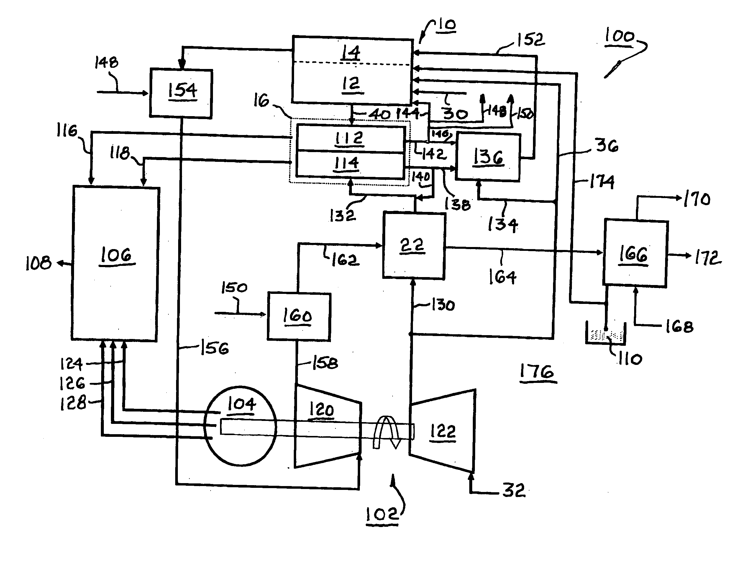
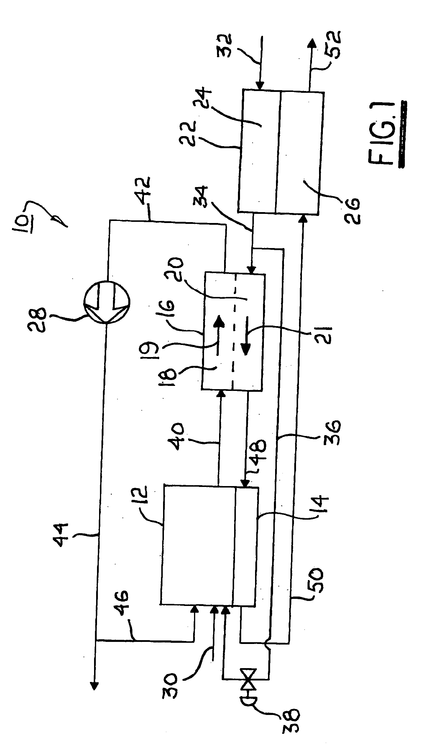
[0026] Referring to FIG. 1, a high temperature fuel cell system 10 includes components known in the art of solid-oxide or molten carbonate fuel cell systems. FIG. 1 is not a comprehensive diagram of all components required for operation but includes only those components necessary to understand the apparatus and method in accordance with the invention. Other components not shown will be readily inferred by those of ordinary skill in the art. A hydrocarbon catalytic reformer 12 includes a heat exchanger 14, preferably formed integrally therewith. A fuel cell stack 16 comprises preferably a plurality of individual fuel cell elements connected electrically in series as is known in the art. Stack 16 includes passageways for passage of reformate across the anode surfaces of the stack, the passageways being shown collectively and schematically as passageway 18. Stack 16 also includes passageways for passage of air across the cathode surfaces of the stack, the passageways being shown colle...


PUM


Abstract

A system for co-generation of electricity combining a hydrocarbon catalytic reformer, an SOFC assembly and a generator driven by a gas turbine. The fuel cell assembly recycles a high percentage of anode exhaust gas into the reformer. Oxygen for reforming is derived from water in an endothermic process. The stack exit temperature is normally above 800° C. DC power from the fuel cell assembly and AC power from the gas turbine generator are directed to a power conditioner. Anode exhaust gas including carbon monoxide and hydrogen is divided into a plurality of portions by which heat may be added to the reforming, gas turbine, and cathode air heating processes. Water may be recovered from the exhaust. A power system in accordance with the invention is capable of operating at a higher total efficiency than either the fuel cell component or the gas turbine component alone.

Description

TECHNICAL FIELD [0001] The present invention relates to means for generating electric power; particularly, to fuel cells and gas turbines; and more particularly, to a hybrid power generating system comprising an interactive solid oxide fuel cell and gas turbine for generating electric power. BACKGROUND OF THE INVENTION [0002] Fuel cells which generate electric current by controllably combining elemental hydrogen and oxygen are well known. In one form of such a fuel cell, an anodic layer and a cathodic layer are separated by a non-permeable electrolyte formed of a ceramic solid oxide. Such a fuel cell is known in the art as a “solid-oxide fuel cell” (SOFC). It is further known to combine a plurality of such fuel cells into a manifolded structure referred to in the art as a “fuel cell stack” and to provide a partially-oxidized “reformate” fuel (“syngas”) to the stack from a hydrocarbon catalytic reformer. [0003] Prior art catalytic partial-oxidizing (POX) reformers typically are opera...

Claims


Application Information

Patent Timeline
IPC IPC(8): F02C1/05F02C1/08H01M8/04H01M8/06H01M8/12
CPCF02C1/05F02C1/08H01M8/04022H01M8/04097Y02E60/50H01M2250/407Y02E20/16Y02E60/563F05D2220/60H01M8/0612
Inventor GRIEVE, MALCOLM J.MACBAIN, JOHN A.RAJASHEKARA, KAUSHIKALEXANDER, GREGORY W.BUCK, BRETT W.RICHEY, DANIEL D.
Owner APTIV TECH LTD
Why Eureka
Try Eureka