Stress-based electrostatic monitoring of chemical reactions and binding

a technology of electrostatic monitoring and chemical reaction, applied in the field of measuring instruments, can solve the problems of stress deflecting diaphragm, change in the size of the gap between the diaphragm and the counter electrode, etc., and achieve the effect of enhancing differentiation and quantitative measurement, and small device siz

Inactive Publication Date: 2005-09-08
CHARLES STARK DRAPER LABORATORY
View PDF14 Cites 14 Cited by
  • Summary
  • Abstract
  • Description
  • Claims
  • Application Information

AI Technical Summary

Benefits of technology

[0014] Because the invention is suitable for silicon micromachining and because of the ability to achieve small device sizes, deployments in arrays are both fe...

Problems solved by technology

Binding results in stresses that deflect the diaphragm and change...

Method used


Image

  • Stress-based electrostatic monitoring of chemical reactions and binding
  • Stress-based electrostatic monitoring of chemical reactions and binding
  • Stress-based electrostatic monitoring of chemical reactions and binding

Examples


Embodiment Construction

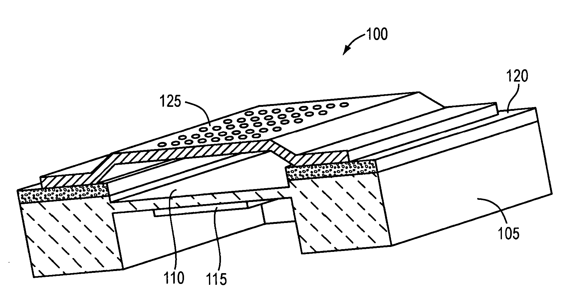
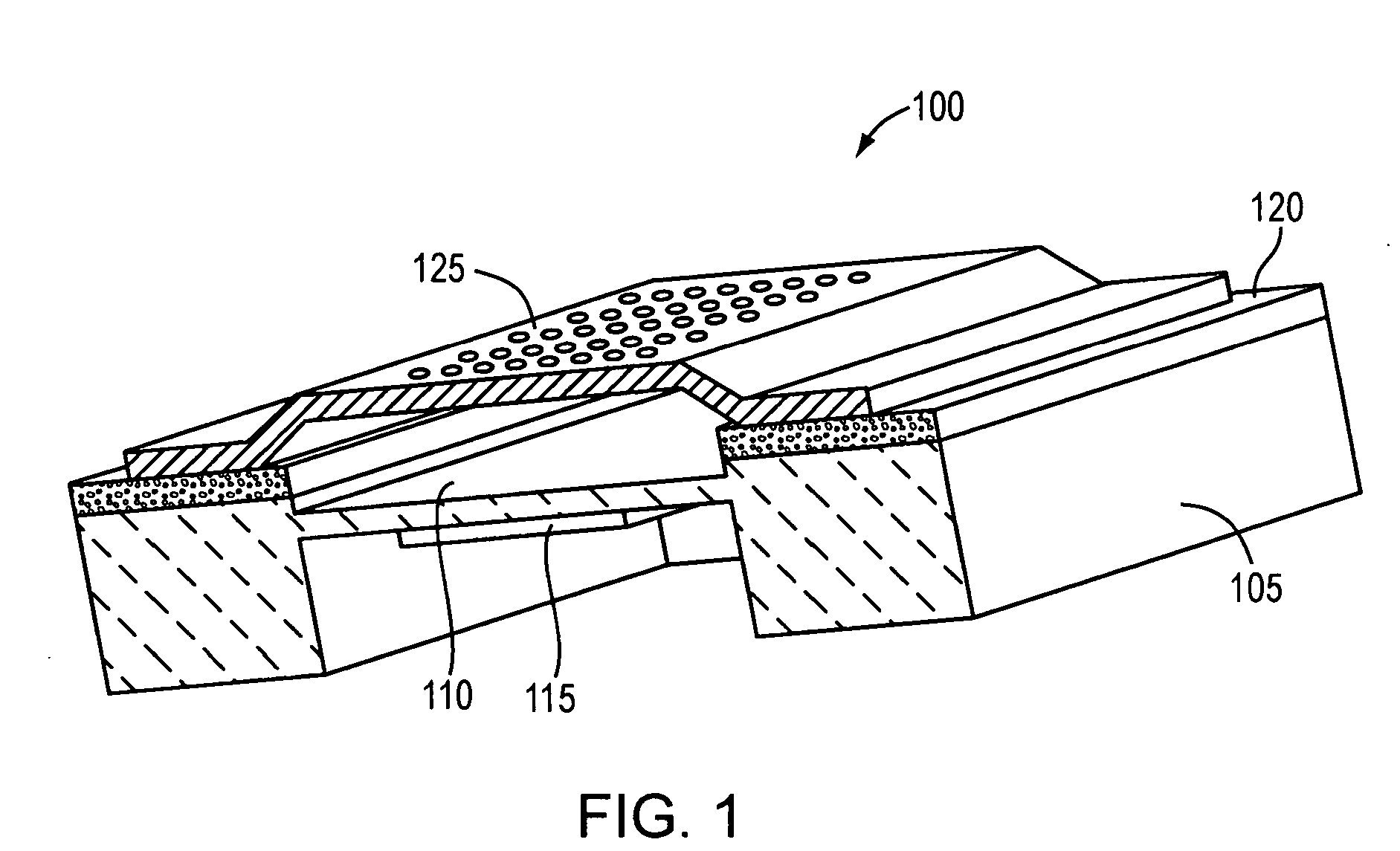
[0025] With reference to FIG. 1, a representative measurement device 100 in accordance with the invention comprises a fixture or substrate 105, which secures the edges of a conductive diaphragm 110. The diaphragm may be circular, rectangular (as illustrated), or other shape. (As used herein, the term “conductive” means electrically conductive or semiconductive, as those terms are understood in the art.) A selective coating 115, described in greater detail below, is applied to the bottom face of diaphragm 110. Since the diaphragm 110 and its support by the substrate 105 are continuous, coating 115 resides within a cavity formed by the substrate.

[0026] An insulating layer 120 (e.g., a coating of rubber or plastic, or an oxide) is provided on a top surface of substrate 105. A counter electrode 125 is secured to the insulating layer 120 in opposition to diaphragm 110, thereby forming a gap between the diaphragm and the counter electrode.

[0027] It is generally important to maintain equ...


PUM

PropertyMeasurementUnit
Pressureaaaaaaaaaa
Concentrationaaaaaaaaaa
Electrical conductoraaaaaaaaaa

Abstract

Electrostatic capacitance measurements are used to detect chemical or biological analytes, or chemical interactions, with great sensitivity. A diaphragm is coated with a material capable of selectively interacting with an analyte of interest, and interaction of the analyte with the coating exerts stresses tangential to the diaphragm's surface. These stresses cause diaphragm displacements that are sensed as varying capacitance.

Description

FIELD OF THE INVENTION [0001] The present invention relates to measurement instruments, and in particular to instruments for measuring analyte binding and the progress of chemical reactions. BACKGROUND OF THE INVENTION [0002] The presence and concentration of analytes, as well as the progress and efficiency of chemical reactions, are typically measured directly—e.g., through optical monitoring if a reaction produces an observable change in light-absorption characteristics, or indirectly—e.g., by changes in mass or volume. Many of the methods typically employed require attachment of a label compound whose properties (i.e., fluorescent, radioactive, chemiluminescent, or absorbing) enable sensitive detection. These methods, however, require development of label reagents, add steps to the detection process, and modify the analyte. In the absence of label compounds, conventional measurements operate on a gross scale, and as a result require substantial amounts of analyte. [0003] Enhanced...

Claims


Application Information

Patent Timeline
IPC IPC(8): C12Q1/68G01N27/00G01N27/22G01N29/02G01N33/543
CPCG01N33/54373G01N2291/02863Y10S436/806G01N27/3276G01N27/227
Inventor WEINBERG, MARC S.BORENSTEIN, JEFFREYDUBE, CHRISTOPHER E.HOPKINS, RALPHCARLEN, EDWIN
Owner CHARLES STARK DRAPER LABORATORY
Why Eureka
Try Eureka