Intervertebral disc implant

Active Publication Date: 2005-09-08
SYNTHES USA
View PDF99 Cites 343 Cited by
  • Summary
  • Abstract
  • Description
  • Claims
  • Application Information

AI Technical Summary

Benefits of technology

[0020] The upper and lower endplates are preferably formed of metal, such as titanium, stainless steel, titanium alloys, cobalt-chromium alloys, or amorphous alloys. Alternatively, however, the upper and lower endplates may be formed of ceramics, composites, polymers, such as poly-ether-ether-ketone (i.e., PEEK) or an ultra high molecular weight polyethylene (i.e., UHMWPE), bone, including cortical, cancellous, allograft, autograft, xenograft, dimineralized or partially demineralized bone, or any other materials able to serve as load bearing supports. The materials chosen for t

Problems solved by technology

A variety of conditions such as spondylolysis, disc herniation, compression of spinal cord nerve roots, degenerative disc disease, and trauma are known to cause severe discomfort, requiring medical attention.
Although intervertebral and posterolateral fusion are widely used, drawbacks to their use include a reduced physiologic range of motion and other fusion related complications such as degeneration of adjacent discs and destabilization of the functional spinal unit.
Although the evolution of spinal arthroplasty and the use of prosthetics in the spine has been similar to that of other joints in the body, evolving from fusing the joint to replacement the functional joint, the advent of spinal arthroplasty, however, has been slower than arthroplasty in other major joints in th

Method used


Image

  • Intervertebral disc implant
  • Intervertebral disc implant
  • Intervertebral disc implant

Examples


Embodiment Construction

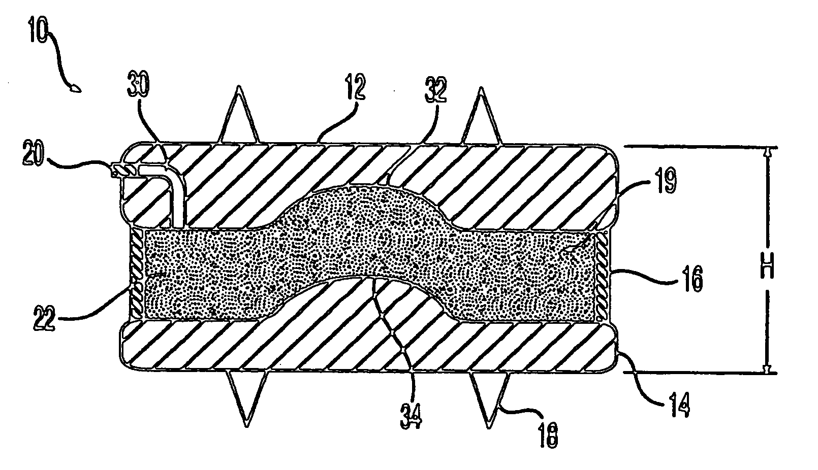
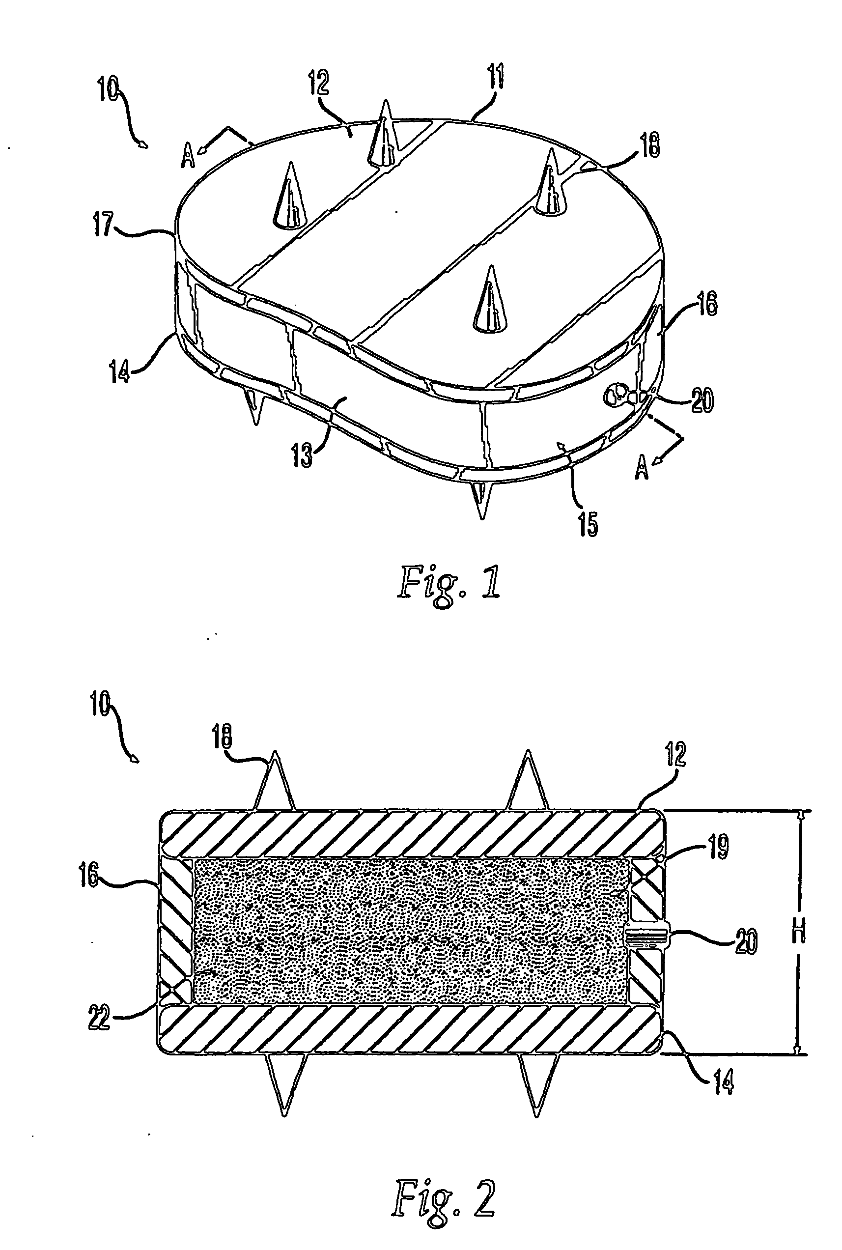
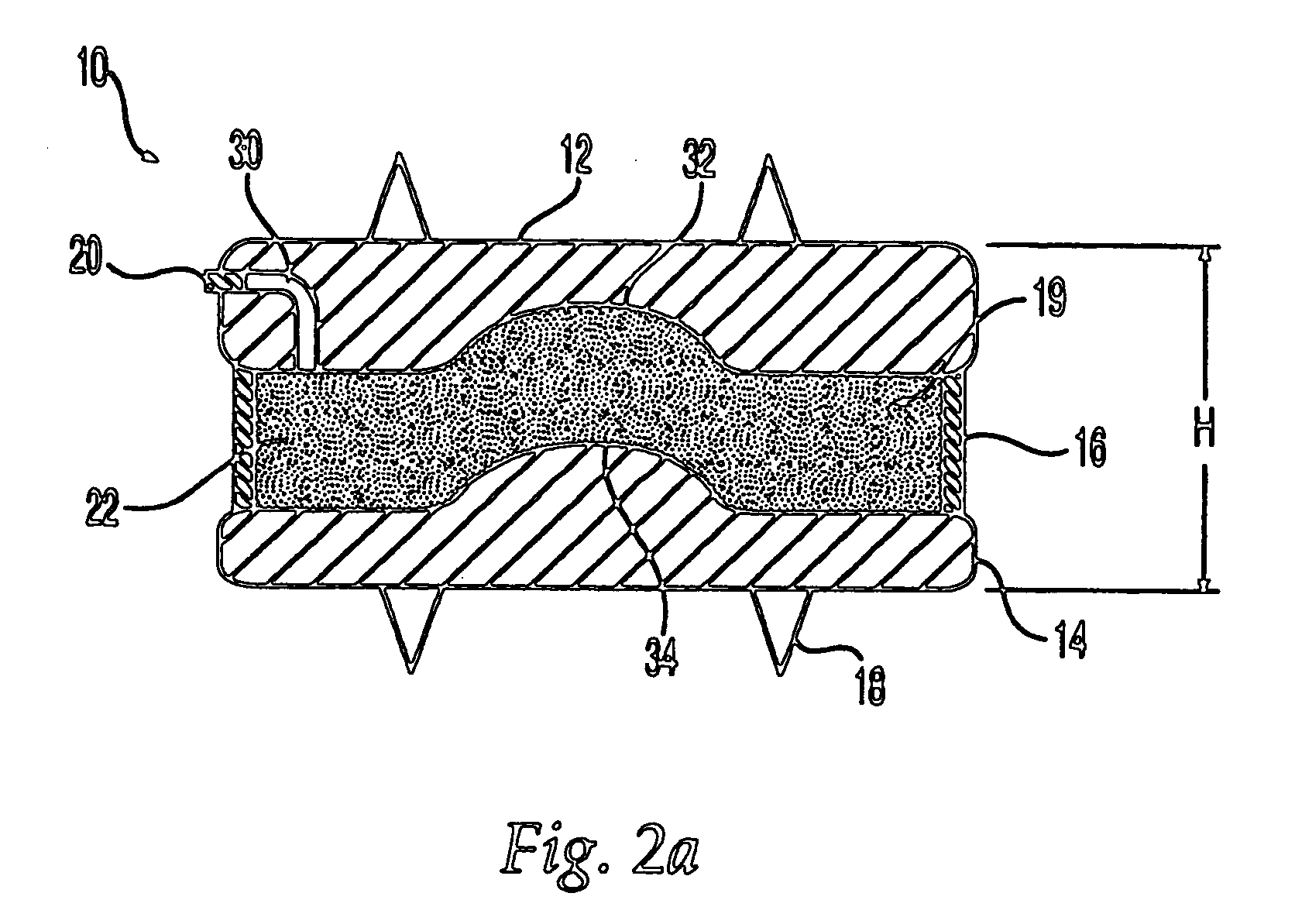
[0049] Any of a wide variety of different implant structures can be prepared according to the teachings shown by the illustrative examples of the intervertebral discs disclosed herein. The intervertebral discs of the present invention are preferably designed to store spinal lordosis, disc height, to allow for a natural range of motion, absorb shock and to provide resistance to motion and axial compression.

[0050] The intervertebral discs preferably are sized and adapted for use in the cervical, thoracic, and lumbar regions of the spine. Also, the intervertebral discs can be tailored for each individual patient allowing for disc characteristics appropriate for the individual patient. For example, the core of the disc can include different assemblies, different components, and / or various types of materials to create the desired characteristics for each individual patient.

[0051] Furthermore, the intervertebral discs may allow flexion, extension, lateral banding, rotation, and translat...


PUM

PropertyMeasurementUnit
Timeaaaaaaaaaa
Lengthaaaaaaaaaa
Elastomericaaaaaaaaaa

Abstract

The invention relates to an artificial intervertebral disc for placement between adjacent vertebrae. The artificial intervertebral disc is preferably designed to restore disc height and lordosis, allow for a natural range of motion, absorb shock and provide resistance to motion and axial compression. Furthermore, the intervertebral disc may be used in the cervical, the thoracic, or the lumber regions of the spine. The artificial intervertebral disc may include either singularly or in combination: an interior at least partially filled with a fluid; a valve for injecting fluid into the interior of the disk; a central region having a stiffness that is preferably greater than the stiffness of the outer regions thus enabling the disc to pivot about the central region. The central pivot may be formed by a center opening, a central chamber, an inner core or a central cable.

Description

CROSS REFERENCE TO RELATED APPLICATION [0001] The present application is a continuation of International Patent Application PCT / US03 / 25535 filed Aug. 15, 2003, which claims priority from U.S. application Ser. No. 60 / 403,356 filed on Aug. 15, 2002 and U.S. application Ser. No. 60 / 403,402 filed on Aug. 15, 2002, the entire contents of which are expressly incorporated herein by reference thereto.FIELD OF THE INVENTION [0002] The invention is related to devices and methods for the treatment of trauma and diseases of the spine. More particularly, the invention relates to intervertebral disc replacement. BACKGROUND OF THE INVENTION [0003] A variety of conditions such as spondylolysis, disc herniation, compression of spinal cord nerve roots, degenerative disc disease, and trauma are known to cause severe discomfort, requiring medical attention. Among the procedures currently used to alleviate such conditions are spinal fusion, such as intervertebral and posterolateral fusion or arthrodesis...

Claims


Application Information

Patent Timeline
IPC IPC(8): A61F2/00A61F2/08A61F2/28A61F2/30A61F2/40A61F2/44A61F2/46
CPCA61F2/08A61F2/28A61F2/30742A61F2/30767A61F2/30965A61F2/441A61F2/4425A61F2/4455A61F2/4611A61F2002/2835A61F2002/30004A61F2002/30014A61F2002/30092A61F2002/30115A61F2002/30125A61F2002/30131A61F2002/30133A61F2002/30187A61F2002/302A61F2002/30326A61F2002/30329A61F2002/30369A61F2002/30377A61F2002/30433A61F2002/30448A61F2002/30451A61F2002/30457A61F2002/30462A61F2002/30472A61F2002/30481A61F2002/30495A61F2002/30563A61F2002/30565A61F2002/30566A61F2002/30568A61F2002/30571A61F2002/30578A61F2002/30579A61F2002/30581A61F2002/30583A61F2002/30584A61F2002/30586A61F2002/30594A61F2002/30604A61F2002/30617A61F2002/30649A61F2002/3065A61F2002/30673A61F2002/30685A61F2002/30772A61F2002/30823A61F2002/30828A61F2002/30838A61F2002/30841A61F2002/30879A61F2002/30904A61F2002/30909A61F2002/30917A61F2002/3092A61F2002/3097A61F2002/4011A61F2002/443A61F2002/4629A61F2002/4631A61F2210/0014A61F2210/0085A61F2220/0025A61F2220/0033A61F2220/0041A61F2220/005A61F2220/0058A61F2220/0075A61F2230/0006A61F2230/0008A61F2230/0013A61F2230/0015A61F2230/0034A61F2230/0065A61F2250/0014A61F2250/0018A61F2250/0037A61F2250/0097A61F2310/00017A61F2310/00023A61F2310/00029A61F2310/00179A61F2310/00407A61F2310/00461A61F2310/0058A61F2310/00796A61F2310/0088A61F2310/00359A61F2002/30367A61F2/44
Inventor COPPES, JUSTIN K.GERBER, DAVIDPAUL, DAVID C.LEE, ANDREW
Owner SYNTHES USA
Why Eureka
Try Eureka