MIG-plasma welding

a plasma welding and plasma technology, applied in plasma welding apparatus, welding media, electrical equipment, etc., can solve the problems of excessive electrode melting, excessive consumption of filler metal, and large welding pool too large to be supported by surface tension in vertical or overhead positions

Active Publication Date: 2005-09-15
WELDOBOT
View PDF11 Cites 41 Cited by
  • Summary
  • Abstract
  • Description
  • Claims
  • Application Information

AI Technical Summary

Benefits of technology

[0016] The present invention relates to devices, systems and methods of welding using combinations of MIG welding and plasma arc welding in which the distances bet

Problems solved by technology

However, the high deposition rate typical to the spray transfer mode may produce a weld pool too large to be supported by surface tension in vertical or overhead positions.
This leads to excessive electrode melting and excessive consumption of filler metal.
The above considerations limit the welding speed and the thickness of the material that may be welded in one pass when operating in any of the three modes, leading to the need for multipass welding with different groove types.
In addition, a large welding pool produces a high level of welding distortion.
Its main drawback is low speed.
The keyhole mode speed is limited by the physical conditions in the weld puddle.
However, these focusing or “magnetic deflecting” coils stabilize only the TIG arc, thus making impossible to control the distance between MIG and TIG arcs at their point of impingement with the workpiece during the welding.
This is a major disadvantage that leads to the substantial reduction of the combined process welding speed and penetration depth.
Moreover, the average heat input is very limited, as is the case in any pulsed current approach vs. continuous current applications.
The particular sequence of the current applied enables only input from only one electrode at a time, thus dramatically reducing the penetration ability of the augmented arc process.
Both torches are connected to the positive and negative terminals of a common power supply, limiting the ability to optimize the energy input by using independed power sources to feed the MIG and TIG electrodes.
Due to the axial feeding of the consumable electrode, it has a long region of contact with the p

Method used


Image

  • MIG-plasma welding
  • MIG-plasma welding
  • MIG-plasma welding

Examples


Embodiment Construction

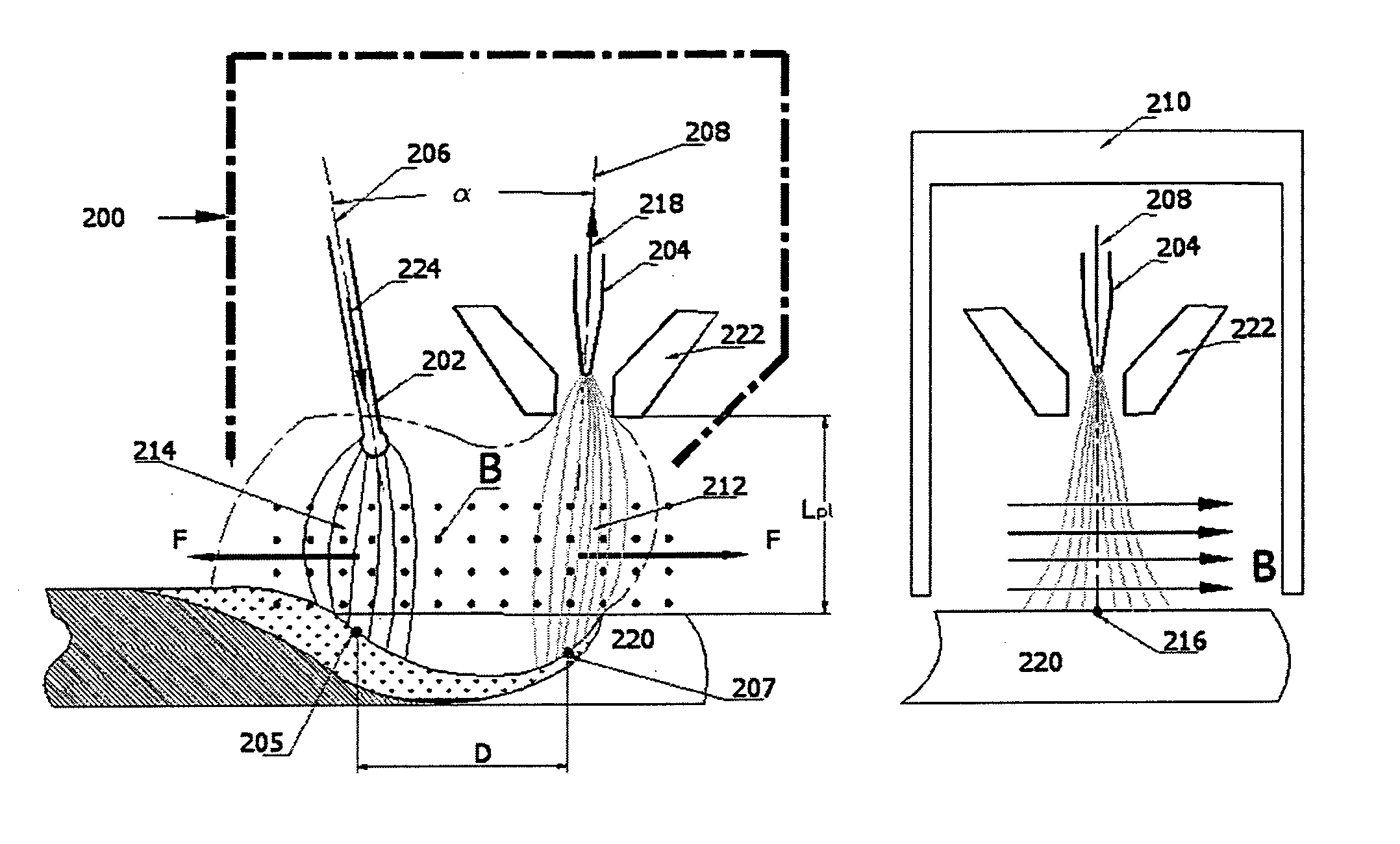
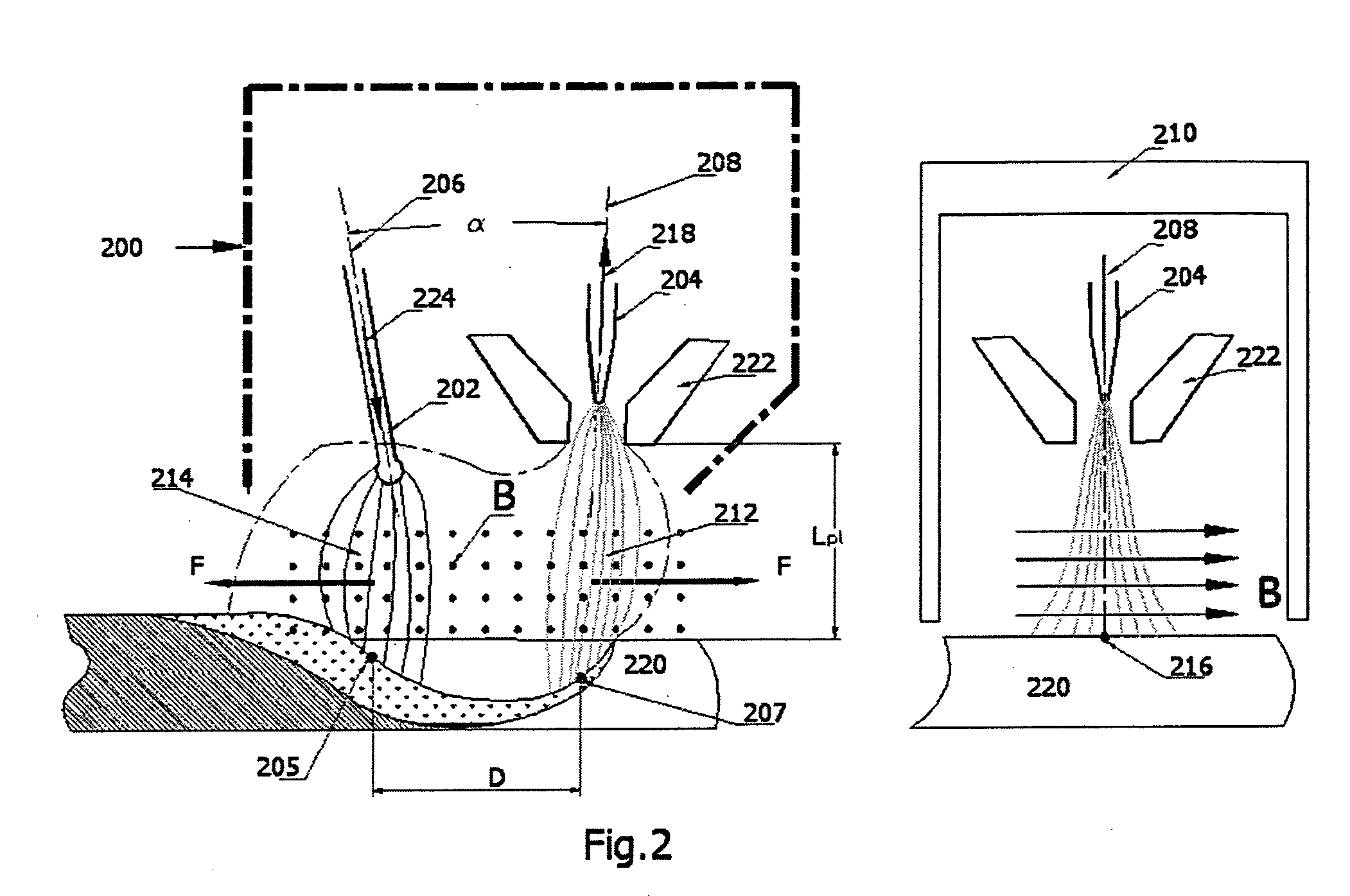
[0042] The present invention is of a device, system and method that combine PAW with MIG welding in a single integrated processing torch, and which enable control of the distance D (see FIG. 2) between arc impingement points on a specimen (workpiece) surface during the welding process.

[0043] A main objective of the present invention is to increase the productivity, quality and robustness of the combined plasma and MIG processes by enhancing the benefits offered by these methods, i.e. the high power density and deep penetration of PAW, and the high arc efficiency and ability to bridge large gaps between workpieces of MIG (GMAW). This goal is attained by combining in a single common-body processing torch 200 (FIG. 2) both a consumable electrode 202 and a non-consumable electrode 204, located in such proximity that assures strong electromagnetic interference between their respective two arcs (a plasma arc 212 and a MIG arc 214) during welding. The invention provides a controllable dis...


PUM

PropertyMeasurementUnit
Angleaaaaaaaaaa
Distanceaaaaaaaaaa
Magnetic fieldaaaaaaaaaa

Abstract

A welding system comprises a combined torch that includes a consumable electrode and a non-consumable electrode positioned so that their respective axes form an acute angle and so that arcs initiated from the electrodes intersect a workpiece plane to define an impingement point distance D, and a magnetic mechanism coupled to the torch and used for controlling the distance D during welding. The magnetic mechanism may be a magnetic shield inserted between the electrodes, or a separate magnetic device, e.g. a permanent magnet or electromagnet.

Description

CROSS REFERENCE TO RELATED APPLICATIONS [0001] The present invention is a continuation in part of application PCT / IL03 / 00953 filed 12 Nov. 2003, which claims priority from U.S. provisional patent application No. 60 / 425,471, filed 12 Nov. 2002, the contents of which are incorporated herein by reference.FIELD AND BACKGROUND OF THE INVENTION [0002] The present invention relates to a system for welding and a method for employing the system, and more particularly to a combination of Metal-Inert-Gas (MIG) welding and Plasma Arc welding. MIG welding technology has been widely known for many years and is broadly used in industrial applications. [0003] The MIG process, also known as Gas Metal Arc Welding (GMAW), incorporates automatic feeding of a continuous consumable electrode that is shielded from the atmosphere by an externally supplied gas. Of special importance is the transfer of metal from the consumable electrode to the workpiece being welded. The transfer may occur via any one of th...

Claims


Application Information

Patent Timeline
IPC IPC(8): B23K9/12B23K9/173B23K10/02H05H1/44
CPCB23K9/173H05H1/44B23K10/02B23K9/1735B23K31/02
Inventor IGNATCHENKO, GEORGIYDYKHNO, IGOR
Owner WELDOBOT
Why Eureka
Try Eureka