Conductive masterbatch and conductive resin composition

a technology of conductive resin and masterbatch, which is applied in the direction of instruments, non-metal conductors, conductors, etc., can solve the problems of poor moldability of polyphenylene ether, unsatisfactory impact resistance of resin composition, and high cost of conductive masterbatch, so as to achieve efficient production

Inactive Publication Date: 2005-09-15
ASAHI KASEI CHEM CORP
View PDF10 Cites 14 Cited by
  • Summary
  • Abstract
  • Description
  • Claims
  • Application Information

AI Technical Summary

Benefits of technology

[0014] Accordingly, it is an object of the present invention to provide a conductive masterbatch which can be advantageously used for producing a conductive resin composition which not only has excellent heat resistance, but also simultaneously exhibits excellent conductivity and impact resistance, so that, when a molded article obtained from the resin composition is subjected to an electrostatic coating, not only is the molded article unlikely to suffer heat distortion and a lowering of the impact resistance, but also an excellent coating can be formed on the molded article due to the excellent conductivity of the resin composition.
[0016] It is still another object of the present invention to provide a method for efficiently producing the above-mentioned conductive resin composition.

Problems solved by technology

However, the moldability of a polyphenylene ether is poor.
Further, the impact resistance of the resin composition was unsatisfactory.
The resin compositions and molded articles obtained by the above-mentioned conventional techniques are likely to suffer heat distortion.
Further, conventionally, it has been impossible to produce a resin composition which is improved with respect to all of the conductivity, impact resistance and heat distortion resistance.
Particularly, the conventional resin compositions were not satisfactory as a material for producing an article (such as an automobile outer panel) which is large in size and which needs to be used in a processing involving an electrostatic coating and needs to have high heat distortion resistance, high impact resistance and conductivity sufficient for electrostatic coating.

Method used


Image

  • Conductive masterbatch and conductive resin composition
  • Conductive masterbatch and conductive resin composition
  • Conductive masterbatch and conductive resin composition

Examples


example 1

[0238] A conductive masterbatch comprising polyamide 6 and conductive carbon black (polyamide 6 / conductive carbon black masterbatch) which is in the form of pellets (master pellets) having a low surface luster was produced in substantially the same manner as in Comparative Example 1, except that the design of the screws of the twin-screw extruder (ZSK-25, manufactured and sold by Krupp Werner & Pfleiderer GmbH, Germany) (used for melt-kneading 92 parts by weight of polyamide 6 and 8 parts by weight of conductive carbon black at a cylinder temperature of 270° C.) was changed. Specifically, the production of the masterbatch was conducted while controlling the melt-kneading conditions (i.e., the rotation rate of the screws, extrusion rate and the like) to obtain master pellets having a surface roughness (average value of the central line average roughness (Ra) values) of 0.3 μm or more (the melt-kneading conditions employed in Example 1 were mild as compared to those employed in Compar...

examples 2 to 4

[0248] In each of Examples 2 to 4, a conductive masterbatch in the form of pellets (master pellets) having a low surface luster was produced in substantially the same manner as in Comparative Example 2, except that the design of the screws of the twin-screw extruder (used for melt-kneading 90 parts by weight of polyamide 6 and 10 parts by weight of conductive carbon black at a cylinder temperature of 270° C.) was changed. Specifically, the production of the masterbatch was conducted while controlling the melt-kneading conditions (the rotation rate of the screws, the extrusion rate and the like) to obtain master pellets having a surface roughness (average value of the central line average roughness (Ra) values) of 0.3 μm or more (the melt-kneading conditions employed in each of Examples 2 to 4 were mild as compared to those employed in Comparative Example 2). (The masterbatches produced in Examples 2, 3 and 4 are referred to as “PA / KB-MB4”, “PA / KB-MB5” and “PA / KB-MB6”, respectively)....

example 5

[0250] A resin composition was produced in substantially the same manner as in Comparative Example 3, except that masterbatch PA / KB-MB5 was fed to the extruder in an amount shown in Table 2 from the 2nd downstream-side inlet, instead of the conductive carbon black. The properties of the resin composition are shown in Table 2, together with the formulation of the resin composition.

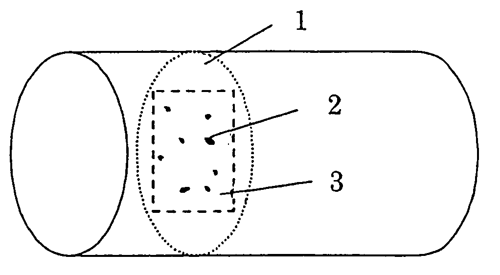
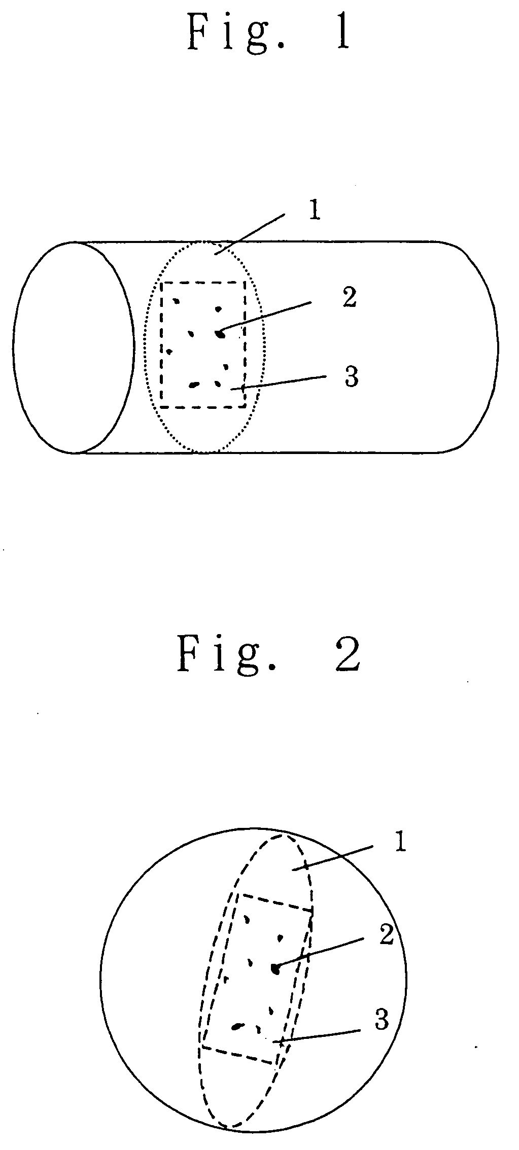
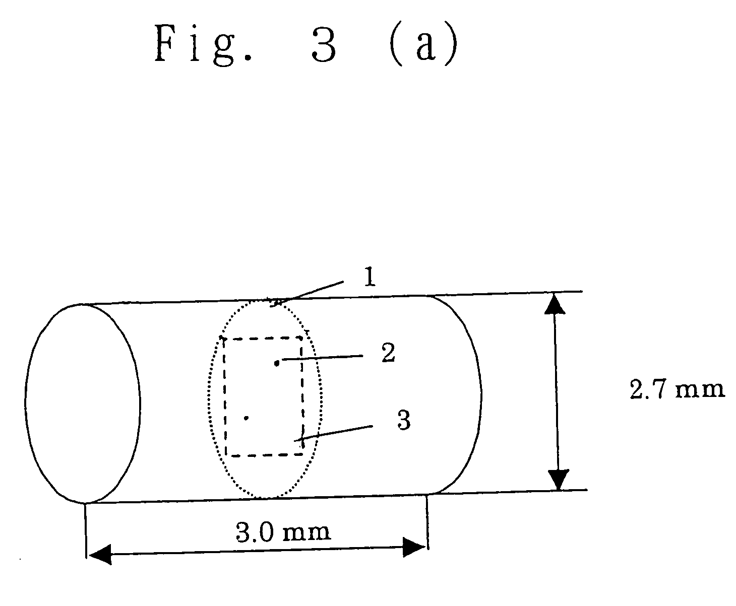
TABLE 2Feeding inletComponentsComp.Comp.Comp.of theof the resinEx. 2Ex. 3Ex. 4Ex. 2Ex. 3Ex. 4Ex. 5ExtrudercompositionUnitsFormulation of the resin compositionInlet providedPPE-1Parts20202020202020at an upstreamM-PPEby14141414141414portion of theSEBS-1weight8.58.58.58.58.58.58.5extruderSEBS-22.52.52.52.52.52.52.51st downstream-PA6636533636363636side inletPA / KB-MB319PA / KB-MB419PA / KB-MB519PA / KB-MB6192nd downstream-PA / KB-MB319side inletPA / KB-MB519KB1.9Results of measurements(with respect to each of masterbatchesPA / KB-MB3, PA / KB-MB4, PA / KB-MB5 and PA / KB-MB6)Number of agglomerated—0—0194444particles(major axis:...


PUM

PropertyMeasurementUnit
areaaaaaaaaaaa
Raaaaaaaaaaa
sizeaaaaaaaaaa

Abstract

Disclosed is a conductive masterbatch comprising a polyamide and conductive carbon black, the conductive carbon black being present in the form of at least one agglomerated particle having a major axis of 20 to 100 μm, wherein the number of the agglomerated particle(s) is 1 to 100 as observed under an optical microscope with respect to a contiguous area of 3 mm2.

Description

[0001] This application is a Divisional of co-pending application Ser. No. 10 / 620,557 filed on Jul. 17, 2003, the entire contents of which are hereby incorporated by reference and for which priority is claimed under 35 U.S.C. § 120. This application claims priority of Application Nos. 2002-377006 and 2003-153159 filed in Japan on Dec. 26, 2002 and May 29, 2003, respectively under 35 U.S.C. § 119, the contents of which are herein incorporated by reference. BACKGROUND OF THE INVENTION [0002] 1. Field of the Invention [0003] The present invention relates to a conductive masterbatch. More particularly, the present invention is concerned with a conductive masterbatch comprising a polyamide and conductive carbon black, the conductive carbon black being present in the form of at least one agglomerated particle having a major axis of 20 to 100 μm, wherein the number of the agglomerated particle(s) is 1 to 100 as observed under an optical microscope with respect to a contiguous area of 3 mm2...

Claims


Application Information

Patent Timeline
Patent Type & Authority Applications(United States)
IPC IPC(8): C08J3/22B29C45/00B29L31/30C08K3/04C08L71/12C08L77/00C08L77/02C08L77/06
CPCC08J3/226C08J2371/12C08J2477/00C08K3/04C08L71/12C08L71/123C08L77/00C08L77/06C08L77/02C08L2666/20C08L2666/22C08L71/00C08J3/22C08K2201/001
Inventor TERADA, KAZUNORINODA, KAZUYA
Owner ASAHI KASEI CHEM CORP
Why Eureka
Try Eureka