Method and device for vibration control

Inactive Publication Date: 2005-09-15
ACTIVE CONTROL EXPORTS INC
View PDF70 Cites 19 Cited by
  • Summary
  • Abstract
  • Description
  • Claims
  • Application Information

AI Technical Summary

Benefits of technology

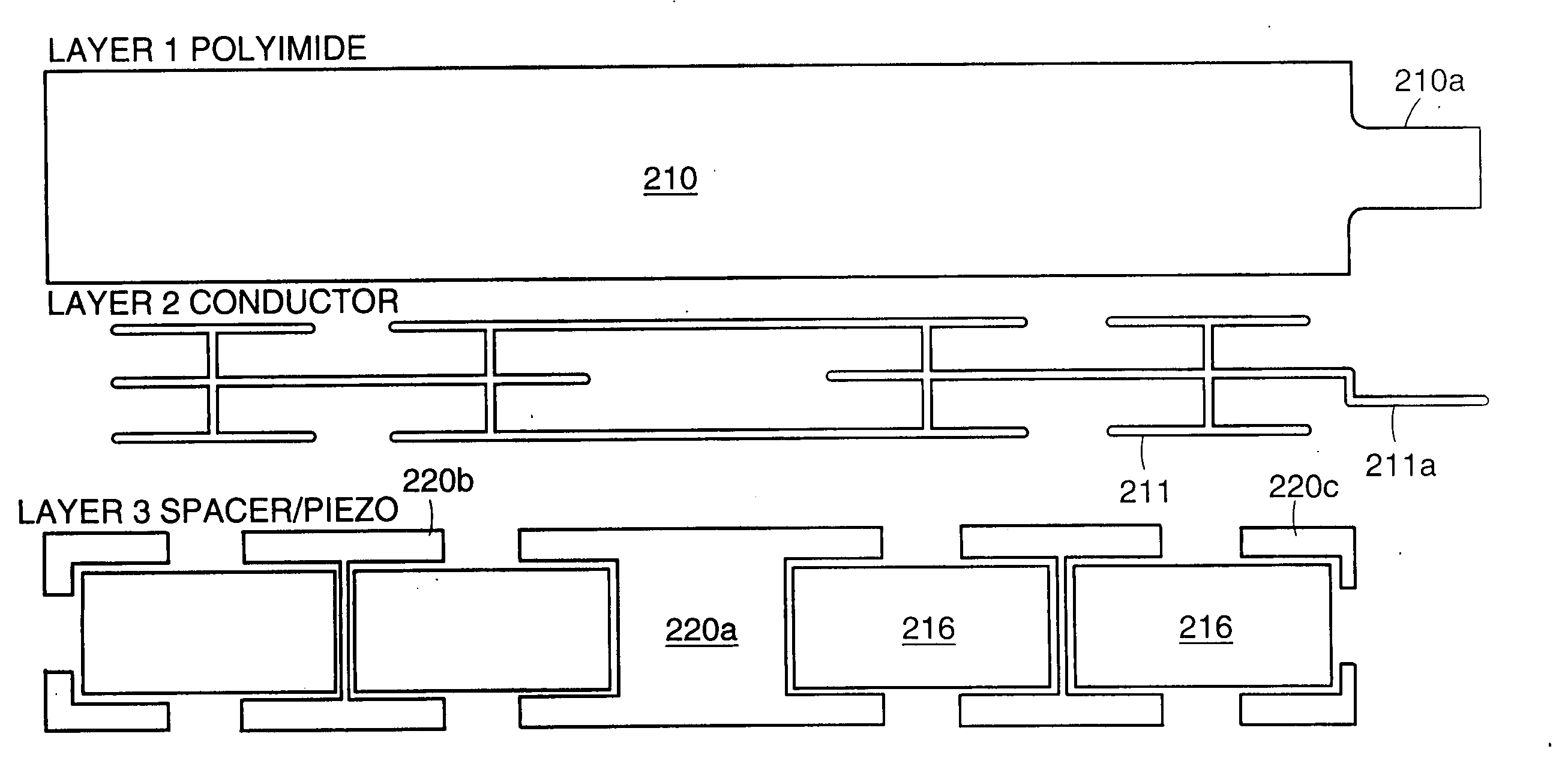
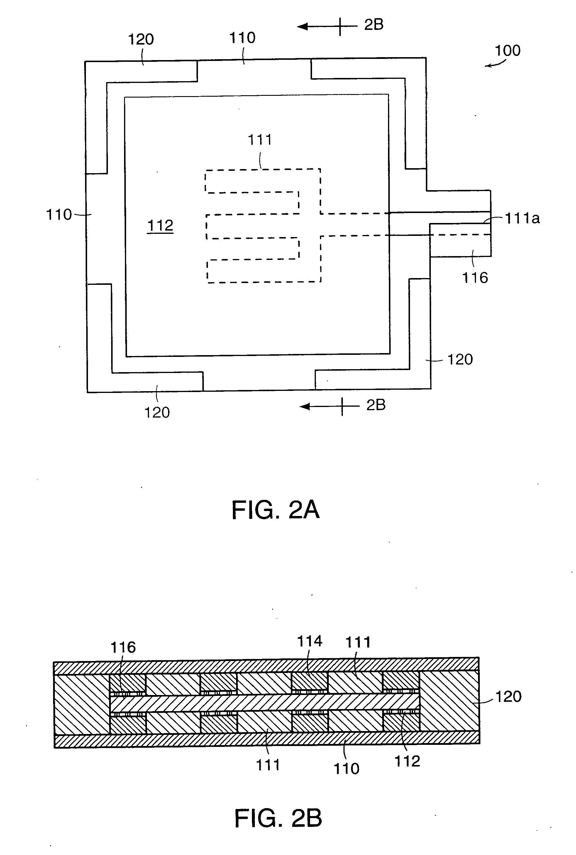
[0023] By way of illustration, an example below describes a construction utilizing rectangular PZT plates a quarter millimeter thick, with length and width dimensions each of one to three centimeters, each element thus having an active strain-generating face one to ten square centimeters in area. The PZT plates are mounted on or between sheets of a stiff strong polymer, e.g., one half, one or two mil polyimide, which is copper clad on one or both sides and has a suitable conductive electrode pattern formed in the copper layer for contacting the PZT plates. Various spacers surround the plates, and

Problems solved by technology

Such an actuator can excite, and therefore control, only the elastic vibration modes of the controlled structure,

Method used


Image

  • Method and device for vibration control
  • Method and device for vibration control
  • Method and device for vibration control

Examples


Example

EXAMPLE 1

[0085] In this example, a vibration control system was designed to determine certain parameters of functional requirements of a gantry active control system. The funtional requirements defined included (but were not limited to) the following: [0086] Accuracy [0087] Settling time [0088] Mass, size and location of the actuators and sensors [0089] Power [0090] Peak strains [0091] Lifetime [0092] Temperature range [0093] Exposure to humidity and solvents [0094] Cost [0095] Interfaces with existing gantry control system

[0096] In order to gather data on the structural response of a gantry during operation, the gantry was equipped with an array of piezoelectric strain sensors and accelerometers. Placement and sizing of the piezoelectric actuators required accurate strain mode shape information, which were obtained from this data, and were compared to the Finite Element Model (“FEM”). One important piece of information obtained in this phase of the project involved the effect of ...

Example

EXAMPLE 2

[0111] A vibration control system in accordance with the invention was used in a lithography machine. As shown in FIG. 16, which shows the power spectral density of error signals recorded by a laser metrology system, use of the vibration control system resulted in a three-fold reduction in system response in the band from 75 to 125 Hz. The reduction in the peak using the vibration control system would be expected to reduce the system image blur by a factor of two-three after conventional methods are used to reduce peaks at 50 Hz and 225 Hz. Alternatively, in some cases, the vibration control system might be used to reduce the peaks at 50 Hz or 225 Hz or at other levels. Reducing the image blur allows the fabrication system to produce finer trace dimensions and feature sizes and improves the accuracy of the feature placement.

[0112] The foregoing description of embodiments and examples of the present invention are presented to demonstrate the range of constructions to which...


PUM


Abstract

A vibration control system comprising an actuator, and a sensor useful for controlling vibrations in systems for fabricating electronics equipment. The actuator may comprise one or more plates or elements of electro-active material bonded to an electroded sheet.

Description

RELATED APPLICATIONS [0001] This application claims the benefit of U.S. Application No. 60 / 117,671, filed Jan. 28, 1999, and is a continuation-in-part of U.S. application Ser. No. 09 / 261,475, filed Feb. 26, 1999, which is a continuation-in-part of U.S. application Ser. No. 08 / 943,645, filed Oct. 3, 1997, which is a contination of U.S. application Ser. No. 08 / 188,145, filed Jan. 27, 1994, the disclosures of each of which are hereby incorporated by reference.BACKGROUND OF THE INVENTION [0002] In the competitive marketplace which exists for automated surface-mount (SMT) electronics equipment, including systems for fabricating electronics equipment or components, improvements in accuracy and speed are a significant advantage. Such equipment is often used in fabricating, for example, semiconductor chips, printed circuit boards, liquid crystal displays, and thin film devices, and may feature multiple gantry / head assemblies, linear motors, photoimaging systems, etching systems, and / or a nu...

Claims


Application Information

Patent Timeline
IPC IPC(8): B06B1/02B06B1/04B06B1/06B06B1/08F16F15/00F16F15/02F16F15/027G03F7/20G05D19/02H01L21/027H01L21/68H01L41/047H01L41/053H01L41/09H04R17/08
CPCF16F15/005Y10T29/53178F16F15/0275F16F2230/08G03F7/70725G03F7/70825G03F7/70833G03F7/709G05D19/02H01L41/047H01L41/053H01L41/0926H04R17/08H01L41/0933H01L41/094H01L41/0946H01L41/0953Y10T29/5313Y10T29/53091Y10T29/53087Y10T29/53039Y10T29/53196Y10T29/42F16F15/02F16F15/00
Inventor SPANGLER, RONALDBIANCHINI, EMANUELEPLETNER, BARUCHMARSH, BETSYJACQUES, ROBERT
Owner ACTIVE CONTROL EXPORTS INC
Why Eureka
Try Eureka