Planar NMR coil with gyromagnetic arc suppression

a gyromagnetic arc and coil technology, applied in the field of resonance coils, can solve the problems of unable to reach (and damage) neighboring capacitor elements, and achieve the effects of minimizing arcing, reducing coil failures, and minimizing the incidence of coil arcing

Inactive Publication Date: 2005-09-15
BRUKER BIOSPIN
View PDF13 Cites 8 Cited by
  • Summary
  • Abstract
  • Description
  • Claims
  • Application Information

AI Technical Summary

Benefits of technology

[0008] In accordance with the present invention, a planar RF NMR coil is provided that greatly reduces coil failures by orienting the capacitive elements within the coil so as to minimize the incidence of coil arcing. The coil, a magnetic resonance radio frequency resonator, generates a magnetic field in an active sample volume, and has a dielectric substrate upon which is deposited a conductive material. The conductive material forms a plurality of nested current carrying loops each of which has magnetic field generating elements and interdigital capacitor elements, and together which form a substantially closed geometric path surrounding an inner region that lies adjacent to the active sample volume. To minimize arcing, the interdigital capacitor elements are oriented in a direction that is substantially parallel to the orientation of the magnetic field generating elements. Since the resonator is configured to be located in a static magnetic field such that the magnetic field generating elements run parallel to the direction of the static magnetic field, the capacitor elements are likewise parallel to the static magnetic field, which thus runs perpendicular to a path between adjacent capacitor elements. The electric field in the capacitor elements is thereby substantially perpendicular to the static magnetic field, and as a result any electron emitted by any of the interdigital capacitor elements will be deflected by the resulting gyromagnetic force and, for typical electric and magnetic field strengths, will not be able to reach (and damage) neighboring capacitor elements.
[0010] The particular layout of the magnetic field generating elements and the interdigital capacitor elements may vary from one coil to the next. However, the coil may benefit from having the capacitor elements in an orientation that ensures a minimum amount of electric field energy in the direction of the static magnetic field. In particular, a good practical orientation would be such that the square of the peak electric field in the direction of the static magnetic field is less than 10% of the sum of the squares of the peak electric fields in each of the two perpendicular directions. In this way, the electric field of the capacitor elements and the static magnetic field remain significantly perpendicular for limiting the incidence of arcing.

Problems solved by technology

The electric field in the capacitor elements is thereby substantially perpendicular to the static magnetic field, and as a result any electron emitted by any of the interdigital capacitor elements will be deflected by the resulting gyromagnetic force and, for typical electric and magnetic field strengths, will not be able to reach (and damage) neighboring capacitor elements.

Method used


Image

  • Planar NMR coil with gyromagnetic arc suppression
  • Planar NMR coil with gyromagnetic arc suppression
  • Planar NMR coil with gyromagnetic arc suppression

Examples


Embodiment Construction

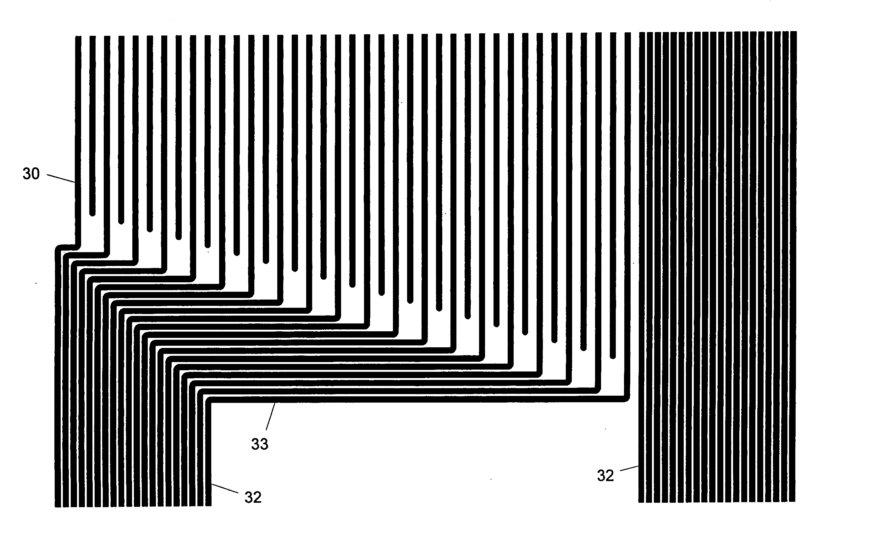
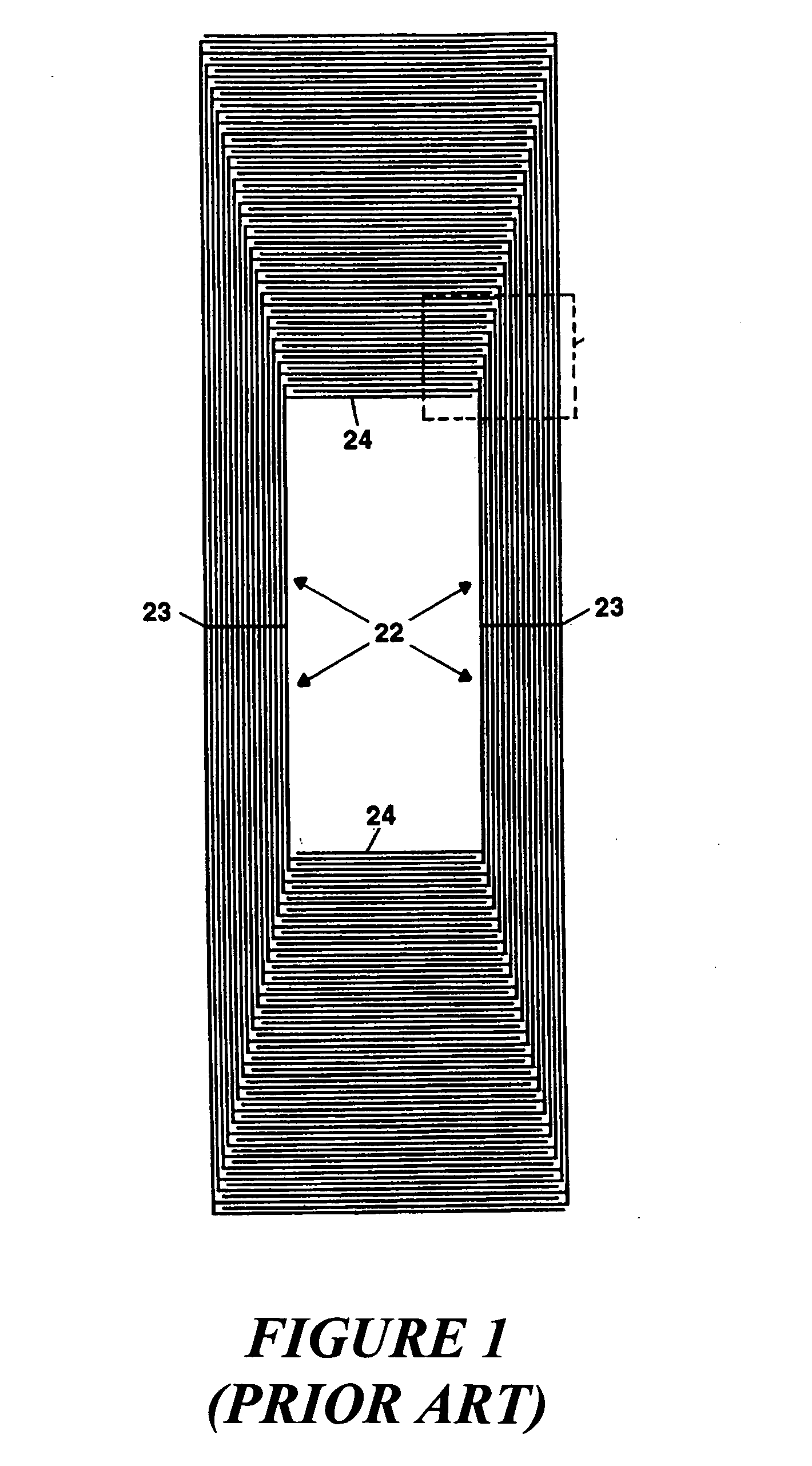
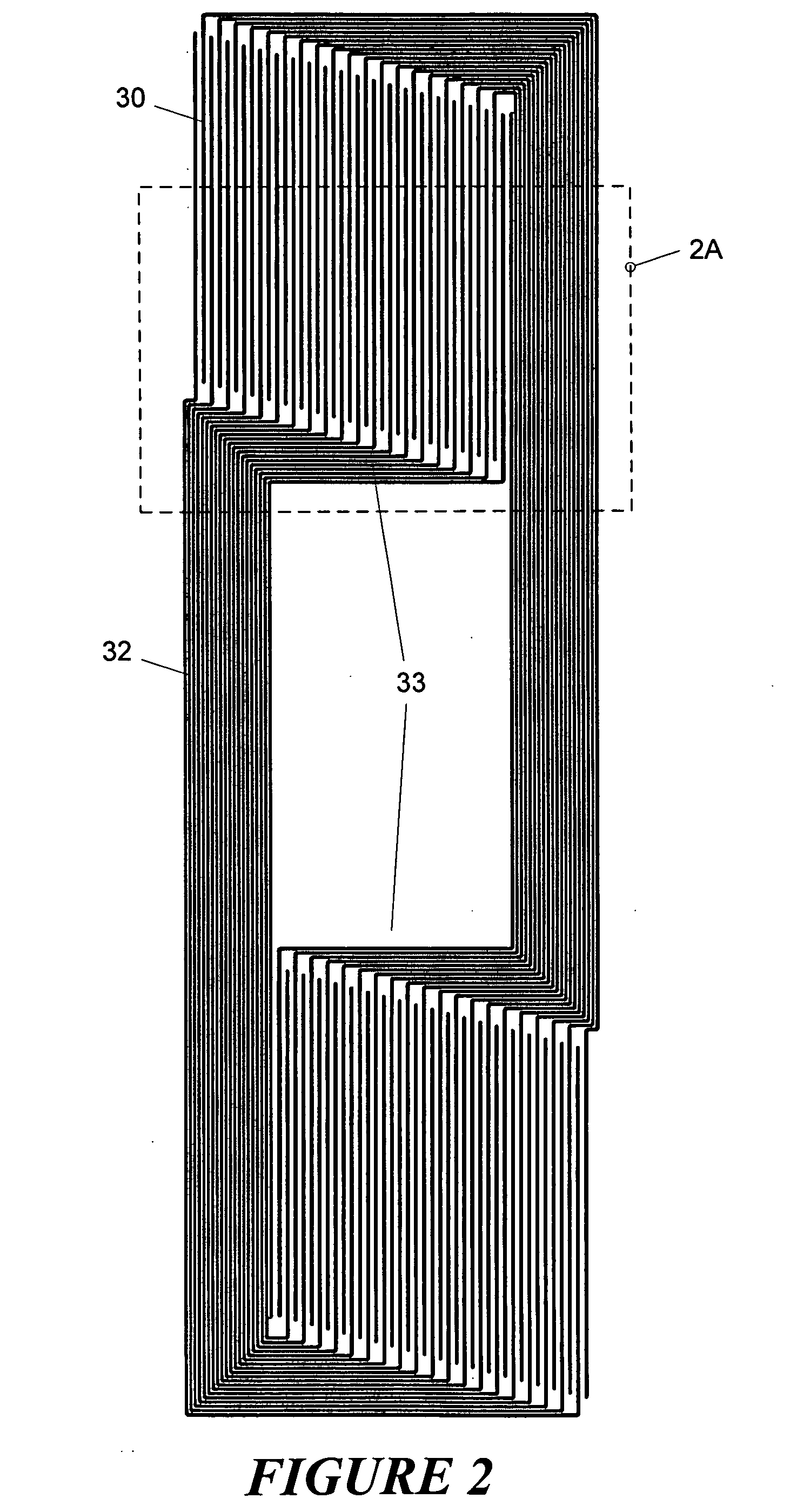
[0021] Shown in FIG. 2 is a schematic view of a first coil embodiment. The view is schematic partly in that it is shown with conductors at an exaggerated scale. That is, in order to depict clearly the configuration of the coil conductors, they are shown much thicker in the drawing figures, and with a correspondingly lower number of conductors per coil. In the coil of FIG. 2, two interdigital capacitors are used, one above the active sample volume and one below it. However, unlike the prior art coil shown in FIG. 1 the capacitive fingers of the FIG. 2 coil are oriented parallel to the vertical magnetic field generating elements. The capacitors are in series, and consist of vertical conductors 30, which are also referred to herein as “fingers.” The capacitors are electrically connected to the magnetic field generating elements 32 via lateral portions 33 of those elements. In this embodiment, all conductors of the coil are a high-temperature superconducting (HTS) material, although the...


PUM


Abstract

A magnetic resonance RF coil comprises a conductive material deposited on a dielectric substrate. The conductive material includes magnetic field generating elements used to generate an RF magnetic field and interdigital capacitor elements. The capacitor elements are oriented parallel to the magnetic field generating elements and, therefore, to a main static magnetic field within which the coil is to be located. This orientation minimizes arcing resulted from emitted electrons and helps to prevent catastrophic breakdown of the coil.

Description

FIELD OF THE INVENTION [0001] This invention relates to radio frequency (RF) probes for nuclear magnetic resonance (NMR) spectroscopy and microscopy and, more particularly, to resonant coils for the transmission and reception of NMR signals. BACKGROUND OF THE INVENTION [0002] In an NMR spectrometer probe, a sample is placed in a static magnetic field which causes atomic nuclei within the sample to align in the direction of the field. Transmit and receive coils, which may be combined in a single coil or set of coils, are placed in the probe positioned close to the sample. The transmit coils apply an RF magnetic field orthogonal to the direction of the static magnetic field, perturbing the alignment of the nuclei. The transmit signal is then turned off, and the resonant RF signal of the sample is detected by the receiver coil. The sensitivity of the spectrometer depends on a number of factors, including the strength of the static field, the closeness of the coupling between the RF coi...

Claims


Application Information

Patent Timeline
Patent Type & Authority Applications(United States)
IPC IPC(8): G01R33/34G01R33/341
CPCG01R33/34007G01R33/34023G01R33/341G01R33/34092G01R33/34053
Inventor WITHERS, RICHARD S.
Owner BRUKER BIOSPIN
Why Eureka
Try Eureka