SINGLE FIBER TRANSCEIVER with FAULT LOCALIZATION

a single fiber transceiver and fault localization technology, applied in the direction of electromagnetic transmission, transmission, electrical equipment, etc., can solve the problems of operator error, unintentional cut of the fiber trunk, increase of inadvertent fiber break, etc., and achieve high optical return loss (orl), without added cost or complexity

Inactive Publication Date: 2005-09-15
OPTICAL ZONU CORP
View PDF7 Cites 157 Cited by
  • Summary
  • Abstract
  • Description
  • Claims
  • Application Information

AI Technical Summary

Benefits of technology

[0008] The present invention provides a single fiber optical transceiver adapted for use in an optical fiber transmission system which is capable of detecting and localizing open fiber connector connection and incidents of high optical return loss (ORL) usually associated with fiber break. The present invention further provides an optical transceiver which can provide such capability without added cost or complexity.

Problems solved by technology

As fiber distribution networks become widely deployed the instances of inadvertent fiber break increases.
For example, such break can be due to construction of a trench somewhere on the fiber route resulting in unintentional cut of the fiber trunk.
Another type of problem can occur for fiber systems occurs where the connections between the transceivers and the optical network is done via “patch panel” that contains an array of fiber-optic receptacle and plugs that enable connections to be configured by an operator.
At times adding or reconfiguring another link may result in an operator error and the wrong fiber is unplugged from the panel.
Service is interrupted and it is not always clear at what end of the link such a mistake took place.
Determining connection problems where fiber disruption is located may involve considerable time and inconvenience to the operator of the network.
Therefore, it will be appreciated that these difficulties related to faults localization in an optical network can waste considerable time and generate associated expenses related to maintenance and system downtime.

Method used


Image

  • SINGLE FIBER TRANSCEIVER with FAULT LOCALIZATION
  • SINGLE FIBER TRANSCEIVER with FAULT LOCALIZATION
  • SINGLE FIBER TRANSCEIVER with FAULT LOCALIZATION

Examples


Embodiment Construction

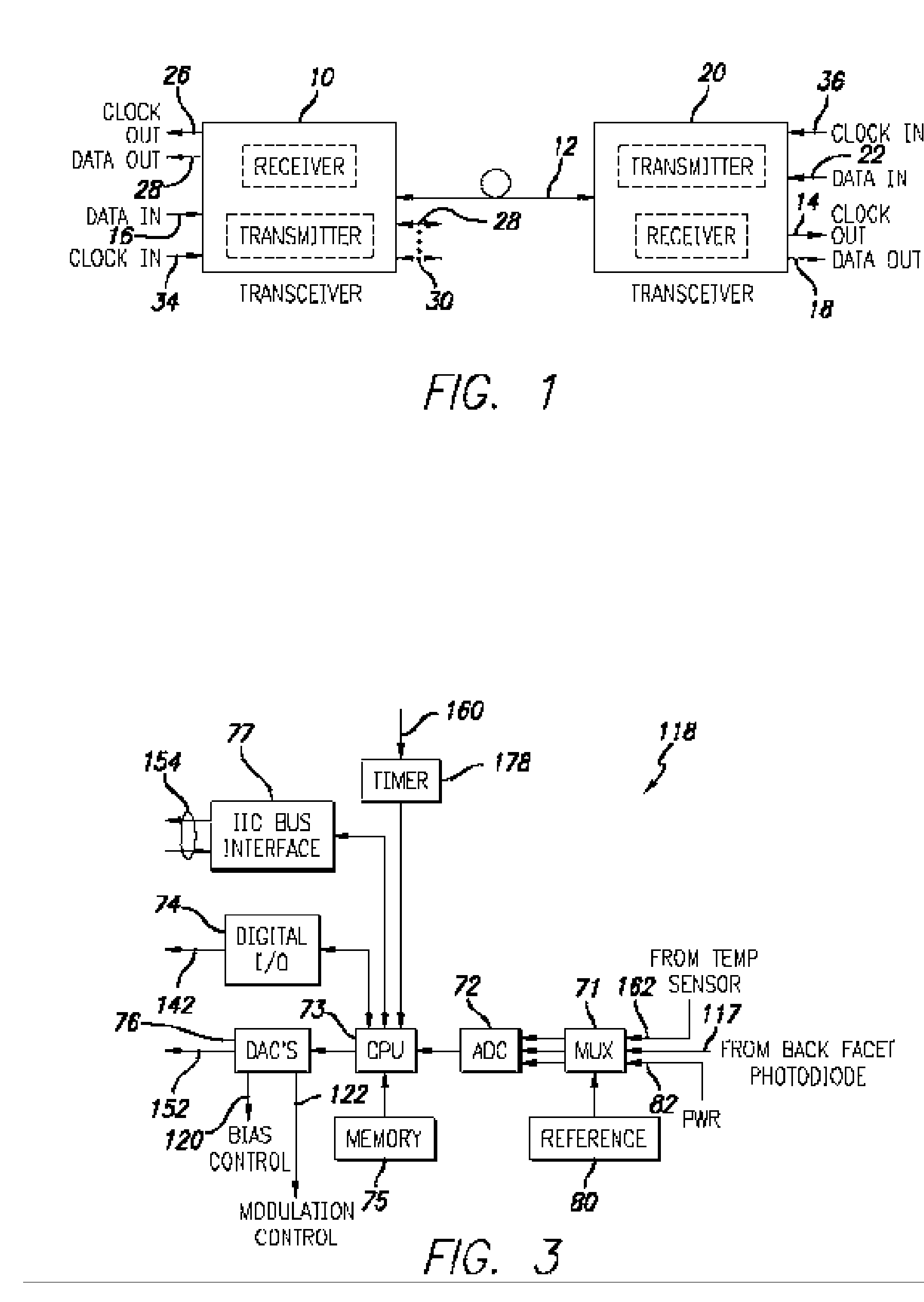
[0022] Referring to FIG. 1, a high-level block schematic drawing of a fiber optic data transmission system incorporating the present invention is illustrated.

[0023] As shown in FIG. 1, a first transceiver 10 is coupled to a second transceiver 20 via optical fiber 12. Both transceiver 10 and transceiver 20 include transmitter circuitry to convert input electrical data signals to modulated light signals coupled into fiber and receiver circuitry to convert optical signals provided along the optical fibers to electrical signals and to detect encoded data and / or clock signals. As indicated by the arrows on the optical fiber 12, transceiver 10 transmits data to transceiver 20 in the form of modulated optical light signals along optical fiber 12 and also receives optical signals from transceiver 20 along the same fiber 12. For example, single wavelength may be employed and both transceivers may transmit and receive at the same wavelength. Alternatively transmission in the two directions m...


PUM


Abstract

A fiber optic transceiver adapted for use in an optical fiber data transmission system is capable of detecting reflection problems in fiber optic links and providing information related to the distance to the point of reflection. The fiber optic transceiver contains a fiber interface, a receiver, a transmitter, and a microcontroller. The microcontroller controls the transmitter to modulate the laser power to transmit impulse test data and the transceiver includes circuitry and microcode to detect reflection due to fiber connection problems. This enables trouble shooting during installation and/or reconfiguring the connection automatically, in response to a connection problem, and provides a physical layer link.

Description

RELATED APPLICATION INFORMATION [0001] The present application claims priority under 35 USC 119 (e) of provisional application Ser. No. 60 / 500,573 filed Sep. 5, 2003, the disclosure of which is incorporated herein by reference in its entirety.BACKGROUND OF THE INVENTION [0002] 1. Field of the Invention [0003] The present invention relates to fiber optic transmitters and receivers and related optical networking systems and methods of transmitting and receiving data along optical networking systems. [0004] 2. Background of the Prior Art and Related Information [0005] Fiber optic data distribution networks are becoming increasingly important for the provision of high bandwidth data links to commercial and residential locations. Such systems employ optical data transmitters and receivers (or “transceivers” when a single unit contain both a transmitter and a receiver) that provide the interface between the electronic circuitry and the fiber optic link. The transceivers are deployed throu...

Claims


Application Information

Patent Timeline
Patent Type & Authority Applications(United States)
IPC IPC(8): H04B10/04
CPCH04B10/071
Inventor BARTUR, MEIRSTEPHENSON, JIM
Owner OPTICAL ZONU CORP
Why Eureka
Try Eureka