
Printed circuit board wireless access point antenna

a wireless access point and printed circuit board technology, applied in the direction of resonant antennas, elongated active elements, protective materials radiating elements, etc., can solve the problems of reducing the service life of conventional wireless access points, affecting reducing the service life of cellular telephone users, etc., to achieve the effect of convenient installation, low cost, and convenient assembly and installation

Inactive Publication Date: 2005-09-22
ANDREW LLC
View PDF18 Cites 9 Cited by
  • Summary
  • Abstract
  • Description
  • Claims
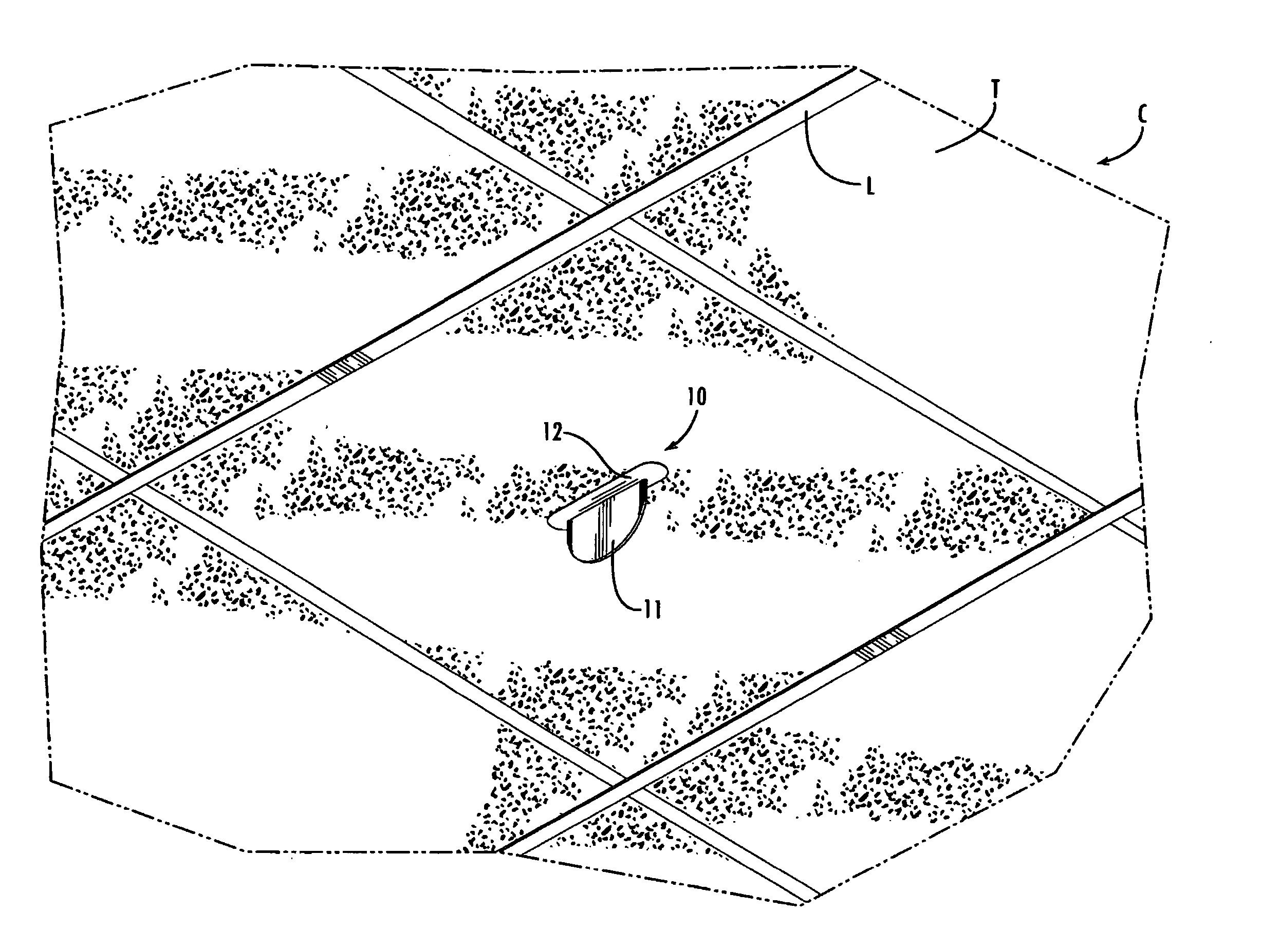
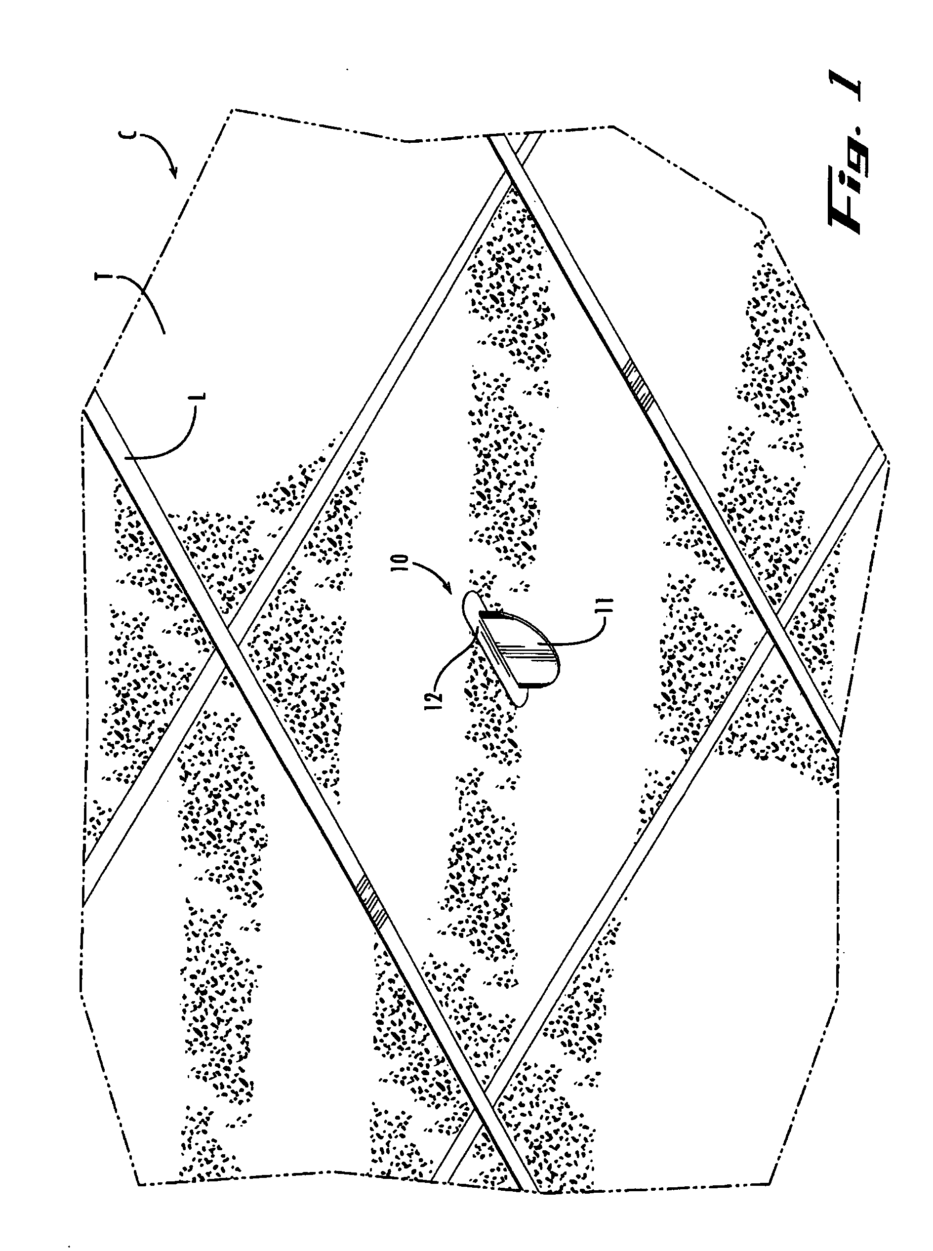
  • Application Information

AI Technical Summary

Benefits of technology

[0008] The needs described above are met in an antenna designed to be assembled and easily installed in a ceiling, such as a conventional ceiling tile or drywall ceiling. The antenna can be manufactured with some of its parts, typically at least an antenna element and an associated cross brace, contained on a printed circuit board (PCB) panel that snaps apart into pieces used to assemble the antenna. The panel may be manufactured as a printed circuit board repeat pattern on a printed circuit board sheet that snaps apart into individual antenna panel units. The individual antenna panels, in turn, have snap apart pieces that can be assembled on site and then installed at the desired location. This configuration makes the antenna element and cross brace inexpensive to mass produce, while also making the antenna easy to assemble and install in the field without the need for tools other than a device to cut the opening in the ceiling. For installation in a conventional tile or drywall ceiling, for example, a standard utility knife is typically sufficient to do the job.
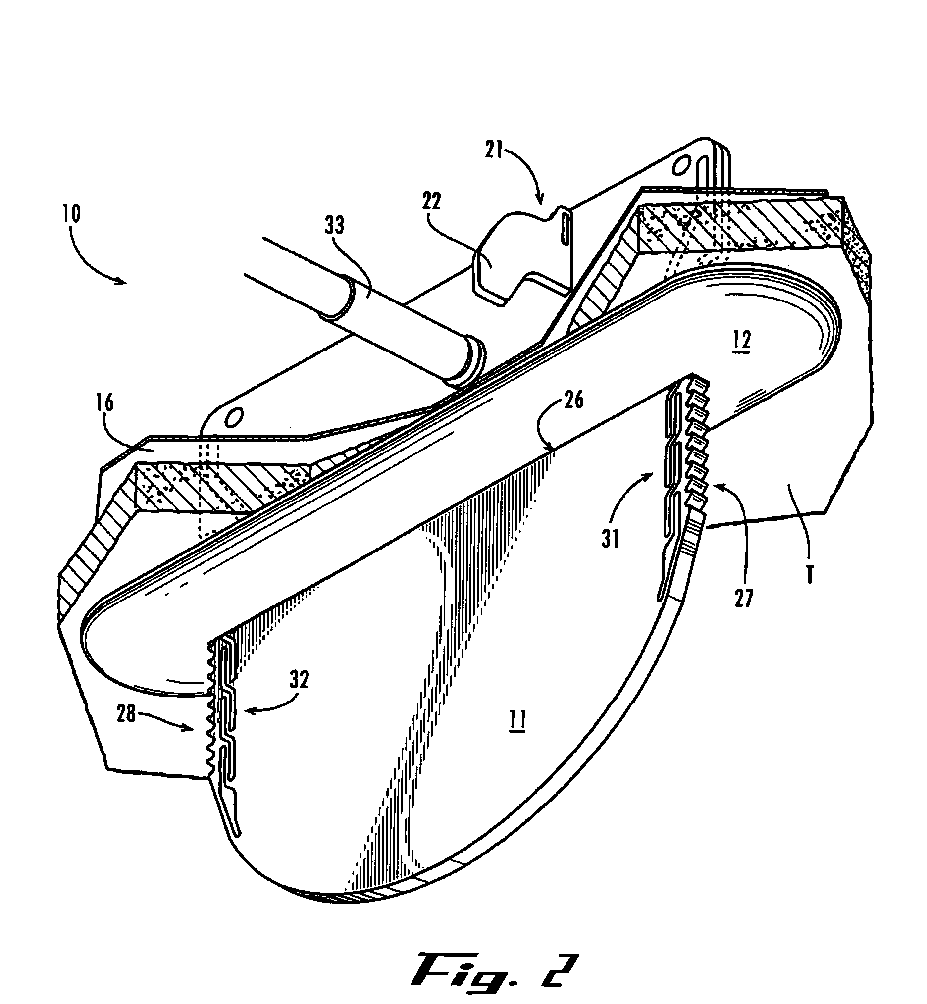
[0009] Each antenna may also be packaged as a self-contained unit including the snap-apart panel, a ground plate, a cable connector and an optional trim piece that fits over the antenna element and conceals the hole in the ceiling. To facilitate assembly and installation of the antenna in the field, the antenna element may also contain printed indicia including assembly instructions and perhaps a logo. This makes the self-contained antenna unit easy to assemble and install in the field with a minimum of tools, as described above.
[0010] The antenna generally includes a fin-shaped antenna element containing a printed circuit monopole conductive radiating element sandwiched between two dielectric boards. The antenna element also includes associated printed circuit transmission signal paths. The fin-shaped antenna element is unobtrusive and has an aesthetically pleasing appearance. The dielectric boards also protect the printed circuit radiating element and associated transmission signal paths, and thereby results in a sturdy assembly that avoids the need for a separate radome to cover the antenna element. This solves many of the problems associated with conventional ceiling-mounted wireless access point antennas.
[0011] The antenna also exhibits exceptional operational characteristics that improve greatly over other available ceiling-mounted wireless antennas. When installed in the ceiling, in particular, the antenna operates for duplex communications within a carrier frequency range from approximately 800 MHz through 2400 MHz to allow the same antenna to be used with currently available PCS, GSM and WiFi systems. The antenna also operates within a coverage pattern below the ceiling extending through approximately 360° azimuth and 180° elevation so that good reception is achieved throughout the room in which the antenna is installed.
[0012] It should also be appreciated that many indoor antennas minimize the size of an associated ground plate for aesthetics and cover the ground plate with a radome because the ground plate is located below the ceiling. The antenna in the present invention locates the ground plate above a ceiling, which allows a larger and more effective ground plate to be used to increase the antenna gain and to direct the energy in a desired direction away from the antenna location without impacting the aesthetic appearance of the antenna.
[0014] In a particular embodiment, the ground plate includes a slot for receiving the antenna element. The antenna element is inserted through the slot so that it extends through the ground plate and through the opening in the ceiling. The antenna element also includes ratchet teeth on its edges and associated strain relief openings adjacent to the ratchet teeth for engaging the slot to hold the antenna element to the ground plate. Alternatively, the antenna element may attach to the ground plate with snap-in feet or another suitable attachment device without extending the antenna element through the ground plate. The antenna element and the cross brace may snap apart from a printed circuit board panel so that the antenna can be easily assembled and installed in the field. The antenna element may also carry printed indicia including assembly instructions for the antenna, and an optional trim piece can be installed over a portion of the antenna element to conceal the opening in the ceiling when the antenna is assembled in the operational configuration.

Problems solved by technology

Virtually every cellular telephone user has experienced a loss or degradation of service in certain indoor locations, particularly in home and business locations.
The reduction in communication coverage or signal strength also causes the cellular telephone to increase its transmit power, which quickly drains the battery.
Unfortunately, conventional wireless access points do not have this bandwidth capability.
Like other known conventional antennas designed for indoor use, however, this antenna only operates at a narrow frequency bandwidth about the 2400 MHz standard for wireless Internet nodes and LAN access points, and therefore cannot also accommodate wireless telephone service.
The eccentric three-dimensional shape of this antenna is relatively expensive to construct and tends to draw distracting attention to the antenna.
Many indoor antennas have other eccentric shapes that are similarly expensive to construct, ungainly and obtrusive.
Often, such antennas also have a somewhat delicate antenna element that needs to be protected from damage by inadvertent contact.
The radome adds to the bulk, complexity and cost of the antenna.

Method used


Image

  • Printed circuit board wireless access point antenna
  • Printed circuit board wireless access point antenna
  • Printed circuit board wireless access point antenna

Examples


Embodiment Construction

[0047] The present invention may be embodied as an antenna configured for easy installation in a ceiling or ceiling tile, although it could be installed in other locations such as a vertical wall, floor, mast or any other suitable location. The antenna is typically configured to provide communication signal strength within generally accepted industry standards for duplex communications in carrier frequency ranges spanning at least an approximate 2:1 ratio of frequency values from the highest to the lowest frequency in the carrier frequency band. For example, a typical antenna is configured to operate in the frequency range from approximately 800 MHz to 2400 MHz. The antenna could, however, be deployed for simplex communications and configured for other operational ranges. The antenna is also configured to provide acceptable communication signal strength in a coverage pattern below the ceiling extending through approximately 360° azimuth and 180° elevation.

[0048] The antennas may ad...


PUM


Abstract

A substantially planar antenna configured for easy installation in a ceiling or ceiling tile. The antenna is configured for duplex communications in carrier frequency ranges spanning at least a 2:1 ratio of frequency values from the highest to the lowest frequency in the carrier frequency band, such as the frequency range from 800 to 960 MHz and 1700 to 2400 MHz, and within a coverage pattern below the ceiling extending through 360° azimuth and 180° elevation. The antennas are manufactured as a printed circuit board that snaps apart into a number of panels, which each contains at least a planar antenna element and a cross brace that are used to assemble the antenna. The printed circuit board is a dielectric substrate carrying printed conductor including a radiating circular monopole disc radiating element, associated transmission signal paths, and printed indicia that typically include assembly instructions and a logo. The printed circuit board sheet configuration makes the antennas inexpensive to mass produce and easy to snap apart into individual units, which are themselves self-contained, easy to snap apart and install.

Description

REFERENCE TO RELATED APPLICATIONS [0001] This Application claims priority to U.S. Provisional Application Ser. No. 60 / 553,883 entitled “Wide-band Communication Access Point” filed on Mar. 17, 2004.FIELD OF THE INVENTION [0002] This Invention pertains to wireless communication systems and more particularly, to an antenna for a wireless communication device, such as a wireless repeater or access point, intended for indoor ceiling mounting. BACKGROUND [0003] In recent years, the proliferation of wireless devices has created a need for support devices, such as wireless repeaters and access points, to maintain service coverage in indoor locations. Virtually every cellular telephone user has experienced a loss or degradation of service in certain indoor locations, particularly in home and business locations. The reduction in communication coverage or signal strength also causes the cellular telephone to increase its transmit power, which quickly drains the battery. To correct this problem...

Claims


Application Information

Patent Timeline
Patent Type & Authority Applications(United States)
IPC IPC(8): H01Q1/00H01Q1/12H01Q1/38H01Q1/40H01Q9/40
CPCH01Q1/007H01Q9/40H01Q1/40H01Q1/1214
Inventor ARNDT, DAVID L.RUNYON, DONALD L.PHILLIPS, SARA ELLEN K.
Owner ANDREW LLC
Learn More