Membraneless and mediatorless microbial fuel cell

a microbial and fuel cell technology, applied in the field of membraneless and mediatorless microbial fuel cells, can solve the problems of secondary pollution, difficult electron transfer to an electrode, and adhesion to the electrode, and achieve the effect of keeping the activity of microorganisms distributed in the anode compartment constan

Inactive Publication Date: 2005-09-22
REMPUS INC
View PDF2 Cites 46 Cited by
  • Summary
  • Abstract
  • Description
  • Claims
  • Application Information

AI Technical Summary

Benefits of technology

[0013] Further, a membrane-less and mediator-less microbial fuel cell according to the present invention can use a buffer solution in an anode compartment in order to maintain the optimum pH for growth of microorganisms in the presence of organic acids generated when artificial wastewater is fed as a fuel so that the activity of microorganisms distributed in the anode compartment is kept constant.

Problems solved by technology

Therefore, in most cases it is difficult for electrons to be transferred to an electrode from the electron transfer reaction occurring in the membrane of the cell.
However, such a mediator is generally a toxic substance and may cause secondary pollution.
The mediator also has disadvantages in that it (i) may adhere to an electrode to decrease overall efficiency when used for a long time; (ii) is an aromatic compound, which are toxic to microorganisms; and (iii) is expensive.
As such, there are limitations to their use.
A cation-exchange membrane, however, has been found to have limitations on the transfer of protons (Gil Geun Cheol et al., Operational parameters affecting the performance of a mediator-less microbial fuel cell, Biosensors & Bioelectronics, 2003, 18, 327-334).
Furthermore, protons generated during metabolism of microorganisms in an anode compartment are not smoothly trarnsferred across a cation-exchange membrane.
This is primarily due to membrane fouling.
Also, it is so expensive that it has cost limitations as a material used for wastewater (sewage) treatment.

Method used


Image

  • Membraneless and mediatorless microbial fuel cell
  • Membraneless and mediatorless microbial fuel cell
  • Membraneless and mediatorless microbial fuel cell

Examples


example 1

The Effect of the Buffering Capacity and the Feeding Rate of Oxygen, which are Rate-Controlling Factors, on a Series of Reactions in a Cathode Compartment

[0033] This example is to identify rate-controlling factors by measuring the electric current generated by using a microbial fuel cell having a cation-exchange membrane and the pH change in a cathode compartment.

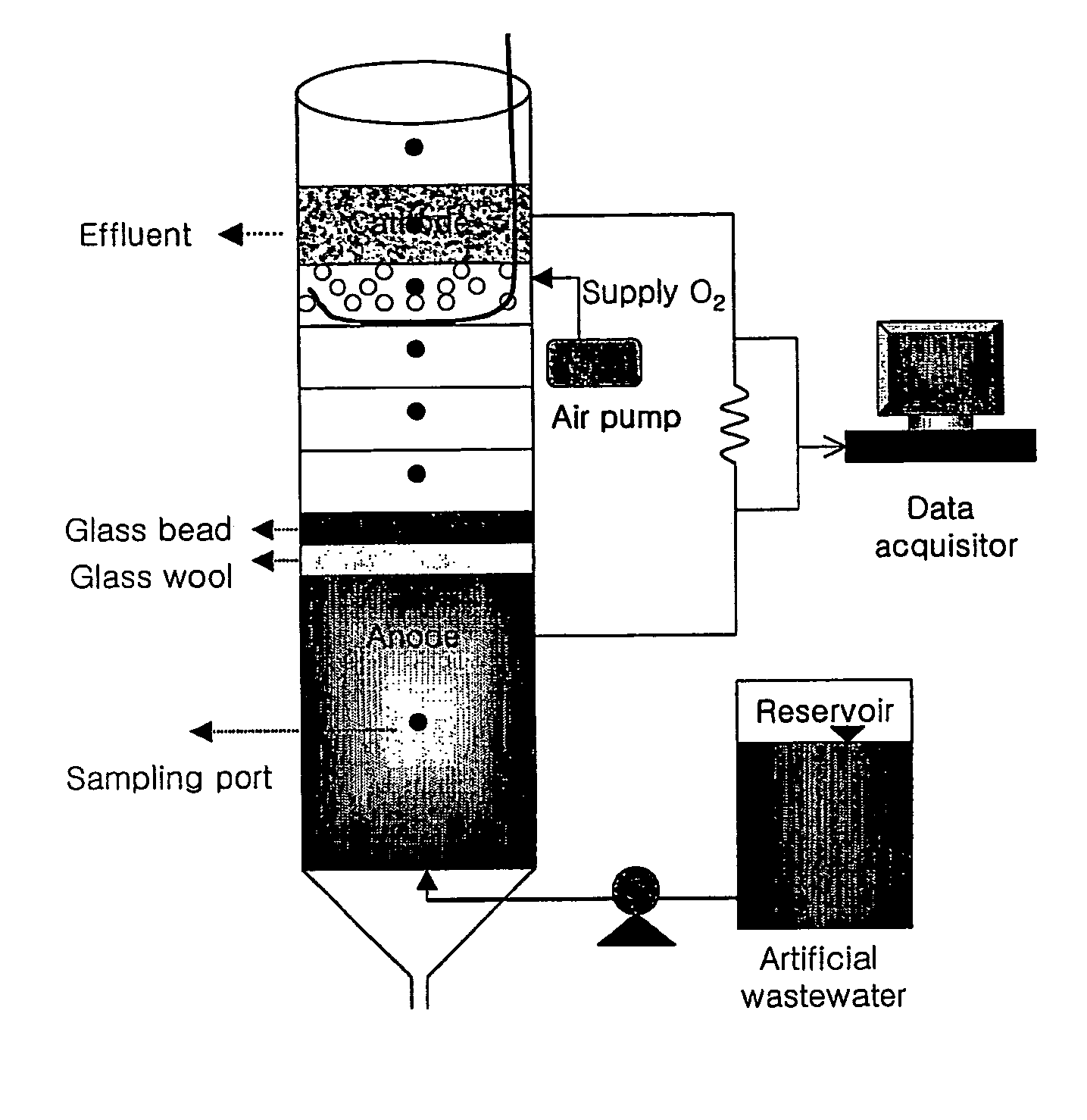
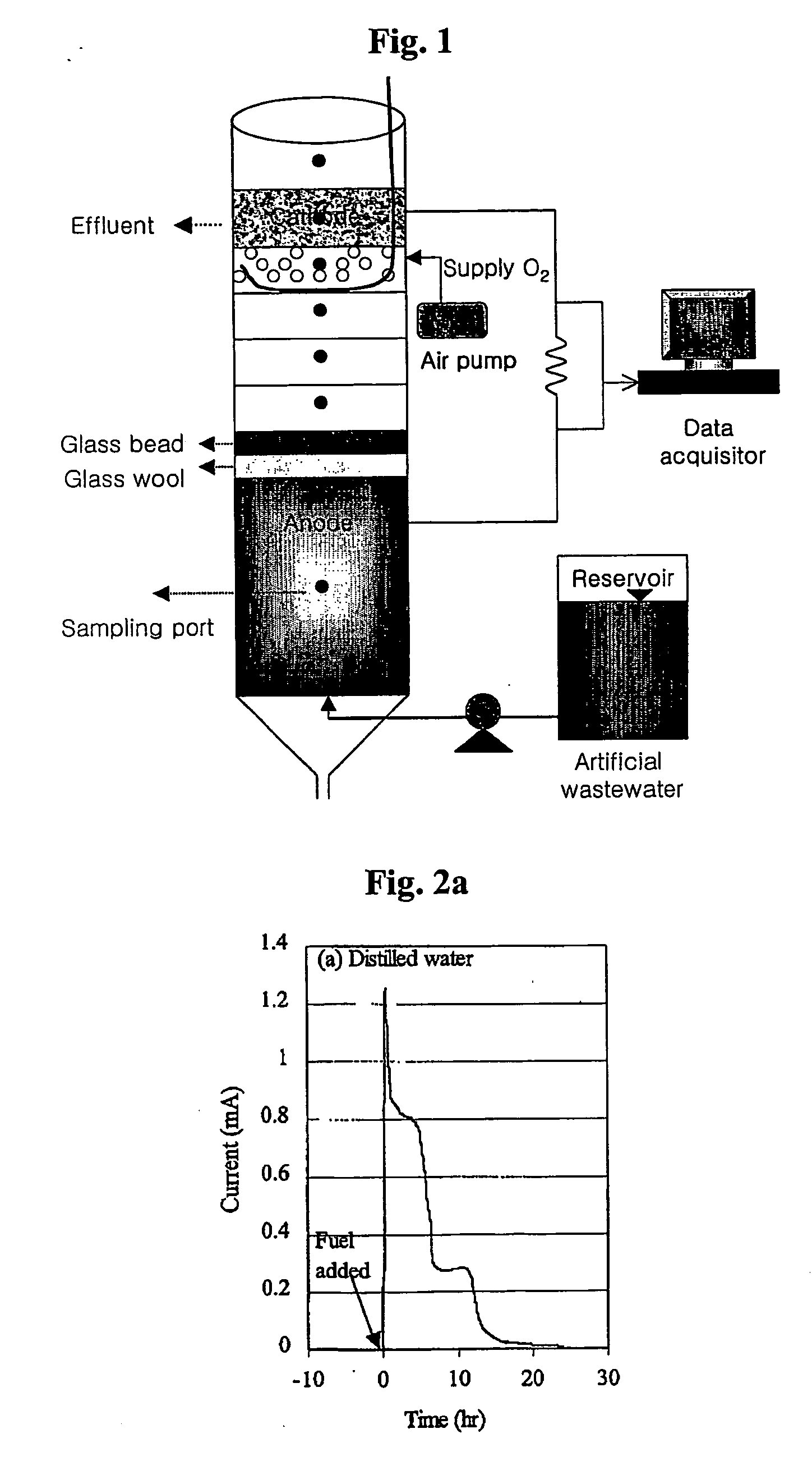
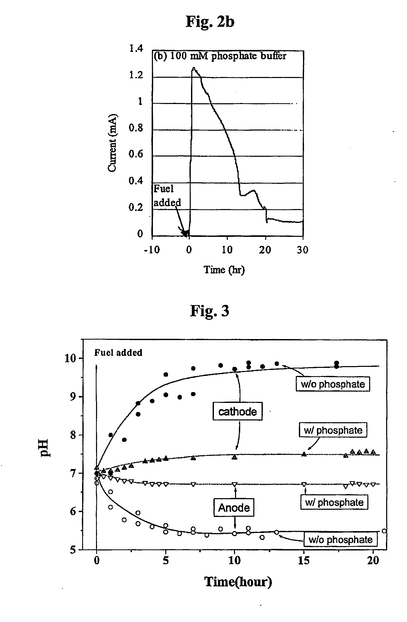
[0034] 10Ω resistance was connected to a mediator-less microbial fuel cell while feeding 400 ppm wastewater to the cell, and the electric current generated was measured to record the results in FIGS. 2a and 2b. Further, the pH in the cathode compartment was measured to record the results in FIG. 3.

[0035]FIG. 2a shows the trend of electric current generated by using distilled water in a cathode compartment. When wastewater was fed as a fuel, an electric current of up to 1.3 mA was generated and then rapidly decreased to maintain around 0.8 mA. The electric current then further decreased to 0.3 mA. The result shows that al...

example 2

Enrichment Culture using a Fuel Cell having no Cation-Exchange Membrane

[0037] This example demonstrates that electrochemically active microorganisms essential to operate a mediator-less microbial fuel cell can be enriched using a fuel cell having no cation-exchange membrane according to the present invention.

[0038] For this purpose, artificial wastewater was used which had components other than organic substances acting as an electron donor, as described in Table 1 below. The inoculation source used for the enrichment culture was the aerobic digester sludge of a sewage disposal plant.

TABLE 1Components other than organic substances in artificial wastewaterComponentsComposition(NH4)2SO40.141gMgSO4.7H2O0.05gCaCl23.75mgFeCl3.6H2O0.25mgMnSO4.H2O5mgNaHCO30.105gTrace mineral solution10mlPhosphate buffer solution (1M, pH 7.0)50mlDistilled water940mlTrace mineral (Balows et al, 1991)Nitrilotriacetic acid (NTA)1.5(g / L)FeSO4.7H2O0.1MnCl2.4H2O0.1CoCl2.6H2O0.17ZnCl20.1CaCl2.2H2O0.1CuCl2.2H2O...

example 3

Effect of the Feeding Rate of Oxygen to the Cathode Compartment on the Performance of a Microbial Fuel Cell

[0042]FIG. 5 shows the result of electric current generated by changing the rate of air fed to a cathode compartment while feeding 300 ppm artificial wastewater to an anode compartment. A microbial fuel cell was operated under conditions such that air was not artificially fed and oxygen was absorbed via the water surface of the cathode compartment. As a result, 0.15 mA electric current was generated. When air was fed at a rate of 60 ml / min, however, the generated electric current slowly increased to 2.1 mA. When the air feeding rate was increased to 200 ml / min, the large change in electric current observed at 60 ml / min was not observed. When the feeding rate was decreased to 20 ml / min, the generated electric current decreased to about 1.7 mA. When air was fed at a rate of 60 m / min, the concentration of dissolved oxygen in a cathode compartment was measured to about 7.5 ppm. Th...


PUM

PropertyMeasurementUnit
heightaaaaaaaaaa
heightaaaaaaaaaa
diameteraaaaaaaaaa

Abstract

Disclosed is a mediator-less microbial fuel cell comprising a cathode compartment, an anode compartment, with or without glass wool and glass bead for separating the two compartments, an element for feeding air to the cathode compartment, and an element for feeding wastewater to the anode compartment. The cell further comprises an element for controlling the distance between the cathode compartment and the anode compartment. Graphite felt or graphite felt coated with a metal such as platinum is used as an electrode of the cathode compartment, and a buffer solution is used in the anode compartment. A mediator-less microbial fuel cell according to the present invention can be operated without using an expensive cation-exchange membrane, of which efficiency is by no means inferior to prior wastewater treatment methods.

Description

TECHNICAL FIELD [0001] The present invention relates to an improved membrane-less and mediator-less microbial fuel cell for treating wastewater. [0002] The present invention is based on the technology of using a microbial fuel cell that converts chemical energy into electrical energy through the metabolism of microorganisms, in which the chemical energy is in the form of organic substances present in wastewater. BACKGROUND ART [0003] It is known that most microorganisms have an outer cellular structure, which shows strong non-conductivity. Therefore, in most cases it is difficult for electrons to be transferred to an electrode from the electron transfer reaction occurring in the membrane of the cell. Thus, a microbial fuel cell using ordinary microorganisms essentially uses an electron transfer mediator in order to transfer electrons from the electron transfer system of the microorganisms to an electrode. However, such a mediator is generally a toxic substance and may cause secondar...

Claims


Application Information

Patent Timeline
Patent Type & Authority Applications(United States)
IPC IPC(8): H01M4/86H01M4/92H01M4/96H01M8/08H01M8/16
CPCH01M4/86H01M4/92H01M4/926Y02E60/527H01M8/08H01M8/16H01M8/0234Y02E60/50H01M8/04
Inventor KIM, BYUNG HONGCHANG, IN SEOPJANG, JAE KYUNGGIL, GEUN CHEOL
Owner REMPUS INC
Why Eureka
Try Eureka