Method for joining laser transmitting resin member and porous member, method for joining thermoplastic resin, and fuel cell

a technology of laser transmitting resin and porous material, which is applied in the direction of cell components, cell component details, electrochemical generators, etc., can solve the problems of deteriorating the airtightness of the cell, affecting the efficiency of the cell, so as to achieve easy laser joining, low production cost, and easy warpage and swelling

Inactive Publication Date: 2005-09-22
HONDA MOTOR CO LTD
View PDF4 Cites 50 Cited by
  • Summary
  • Abstract
  • Description
  • Claims
  • Application Information

AI Technical Summary

Benefits of technology

[0047] Further, conventionally, warpage and swelling easily occur on a pressed separator composed of a resin frame and the electrode portion which is thinly formed after molding, application of a liquid seal or the like is carried out with very low productivity, and thus it is difficult to form a cell. In the present invention (the seventh to the twenty-seventh aspects of the invention), however, even if warpage and swelling occur in the separator at the time of the joining process, the joining interface is adhered by a transparent retaining jig made of glass, acrylic resin, PC or the like which can be corrected at the time of laser joining, so that the laser joining is easy. For this reason, high productivity can be realized.

Problems solved by technology

When, therefore, the techniques disclosed in the Patent Documents 2 to 4 are used so that resins are joined, plural kinds of members are required, and thus the production cost is high.
Further, in the technique disclosed in the Patent Document 7, although the problem of the durability of the PEM can be solved, the separator is independent from the MEA, and excellent laminated assembly property cannot be realized.
When a defective cell is replaced, a sealing position of another cell shifts, thereby deteriorating the airtightness of the cells.
The cells can be assembled by using the liquid seal, but since the assembly requires high-temperature calcination, this possibly exerts a harmful influence on the membrane and the catalyst of MEA.
As a result, calcinating temperature and time are limited, and thus excellent productivity cannot be realized.
Since the MEA is manually located in such cases, a shift occurs at the time of assembly, and various defects occur.
This excellent resistivity is, however, attenuated by drying of the membrane.
For this reason, a pin fastening portion occupies a large area, and thus it is difficult to miniaturize the fuel cell.
Since, however, the seal material is used, it is difficult to completely prevent the drying of the membrane.
This technical literature, however, does not describe that this technique can be applied to the fuel cell, and such a use is not examined.

Method used


Image

  • Method for joining laser transmitting resin member and porous member, method for joining thermoplastic resin, and fuel cell
  • Method for joining laser transmitting resin member and porous member, method for joining thermoplastic resin, and fuel cell
  • Method for joining laser transmitting resin member and porous member, method for joining thermoplastic resin, and fuel cell

Examples


example 1

PRACTICAL EXAMPLE 1

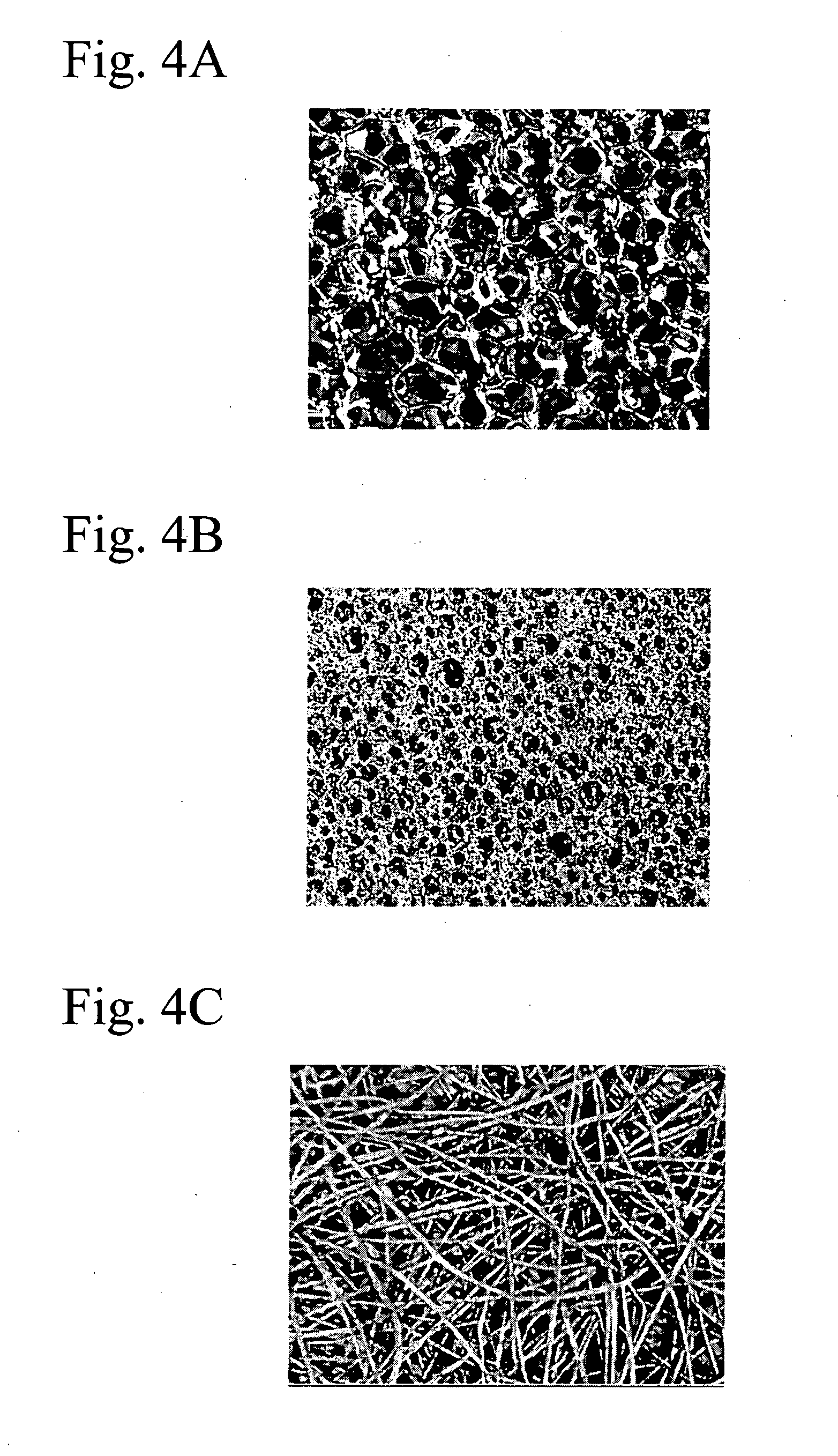
[0209] As to the joining form shown in FIG. 9, metallic foam shown in FIG. 4B is used as the porous member 31, PEEK is used as the laser transmitting resin member 32, and a laser beam is emitted from above in FIG. 9 so that they are joined. FIG. 12A is a cross sectional view illustrating a joined body obtained in such a manner, and FIG. 12B is a vertical sectional view illustrating the joined body. As is clear from FIG. 12A, pores with diameter of 20 to 50 μm formed by the metallic foam are sufficiently impregnated with the resin. As is clear from FIG. 12B, although residual pores (white portions in the drawing) are present in the joined body, the pores are sufficiently impregnated with the resin in the thicknesswise direction. As a result, the peel strength of the joined body shown in FIGS. 12A and 12B is sufficiently three-dimensionally secured.

EMBODIMENT OF THE THIRD TO THE SIXTH ASPECTS OF THE INVENTION

[0210]FIG. 13 is a conceptual diagram illustrating one p...

example 2

PRACTICAL EXAMPLE 2

[0237] A Practical Example of the invention is explained in detail below, and the effects of the present invention are substantiated.

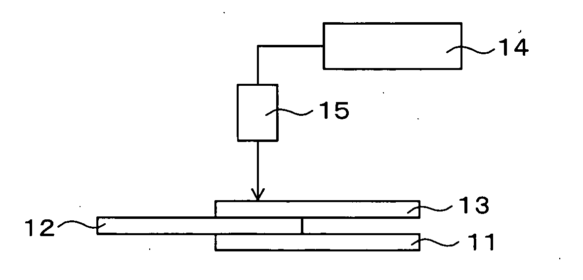
[0238]FIG. 24 is a conceptual diagram illustrating a resin joining form for substantiating the effects of the present invention. As shown in FIG. 24, laser transmitting thermoplastic resins 311 and 312 and a laser absorbing thermoplastic resin 313 are laminated, and a laser beam with wavelength of 940 nm is emitted from above in a direction of an arrow 314. The joined states of predetermined places 315 and 316 of the interfaces between the resins 311 to 313 are determined. Laser transmission efficiency of the laser transmitting thermoplastic resins 311 and 312 is 15.9%, their melting points are 282° C., and specific heat at constant pressure at 282° C. is 1.8 kJ / kg·K, a target value of the melting thickness is 0.19 mm, and specific gravity is 1.77 g / cm3.

[0239] In this Practical Example, the joined states in Experimental examples 1 ...

example 3

PRACTICAL EXAMPLE 3

[0241] As shown in FIG. 25, the laser transmitting thermoplastic resins 317 and 318 are laminated, laser with wavelength of 940 nm is emitted from above to a direction of an arrow 319 under the same conditions as those in the Experimental Example 6 where the preferable results are obtained in the Practical Example 2 (see corresponding portions in Table 1). The joined state of a predetermined place 320 of the interface between the resins 317 and 318 is determined as a confirmation work. The laser transmission efficiency of the laser transmitting thermoplastic resins 311 and 312 is 15.9%, and their melting point is 282° C., specific heat at constant pressure at 282° C. is 1.8 kJ / kg·K, a target value of the melting thickness is 0.19 mm, and specific gravity is 1.77 g / cm3.

[0242] As a result, it is confirmed that the joined state is satisfactory, and thus as shown in FIG. 25, even in the case where the laser absorptive thermoplastic resin is not laminated on the botto...


PUM

PropertyMeasurementUnit
viscosityaaaaaaaaaa
thicknessaaaaaaaaaa
diameteraaaaaaaaaa

Abstract

A method for joining a resin member and a porous member can prevent peeling in a specified direction. When a thermoplastic laser transmitting resin member and a porous member are joined, the laser transmitting resin layer and the porous member are laminated, and a laser beam is emitted at a side of the laser transmitting resin member. The porous member is heated so that the laser transmitting resin member is melted, and the melted resin is impregnated with holes of the porous member. The resin is cooled so as to solidify.

Description

BACKGROUND OF THE INVENTION [0001] 1. Field of the Invention [0002] The present invention relates to a method for joining a laser transmitting resin member and a porous member, a method for joining thermoplastic resin, and a fuel cell. The invention specifically relates to a joining technique in which peel strength of a joined body which is to be obtained is improved, a joining technique which realizes ease of material handling, reduction in the manufacturing cost and an excellent laminated assembly so as to realize satisfactory airtightness of a cell, and a technique for producing fuel cells that miniaturizes the fuel cells and realizes excellent resistivity of a proton exchange membrane (hereinafter, simply referred to as “PEM”). [0003] 2. Description of the Related Art [0004] The techniques of joining laser transmitting resin members and porous members have various uses, and this technique can be applied to, for example, membrane electrode joined bodies and cell structures of the...

Claims


Application Information

Patent Timeline
Patent Type & Authority Applications(United States)
IPC IPC(8): B29C65/16H01M2/08H01M8/02
CPCB29C65/1616B29C65/1654B29C66/1122B29C66/30326B29C66/43B29C66/742B29K2071/00B29K2081/04B29K2305/00H01M8/0206H01M8/0273H01M8/0284H01M8/0297Y02E60/50B29C65/44B29C66/727B29C65/1635B29C66/71B29C66/7392B29C66/73921B29C66/7394B29C66/8322B29K2083/00B29K2069/00H01M8/0258H01M8/0267H01M8/241H01M8/2457
Inventor ENJOJI, NAOYUKIKOMATSUKI, MASATO
Owner HONDA MOTOR CO LTD
Why Eureka
Try Eureka