Device for connecting a cardiac biventricular assist means

US20050209502A1Inactive Publication Date: 2005-09-22DEUTSCHES ZENTRUM FUER LUFT & RAUMFAHRT EV

Image

  • Device for connecting a cardiac biventricular assist means
  • Device for connecting a cardiac biventricular assist means
  • Device for connecting a cardiac biventricular assist means

Examples


Embodiment Construction

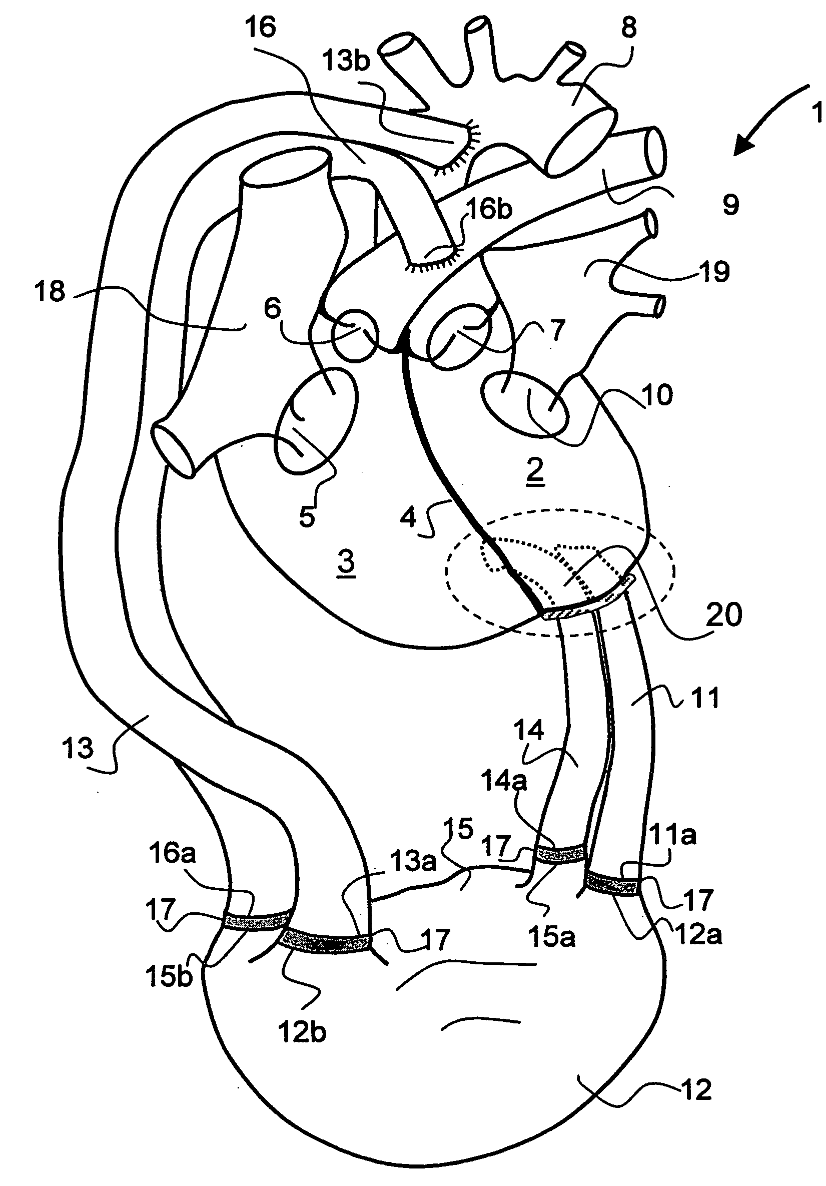
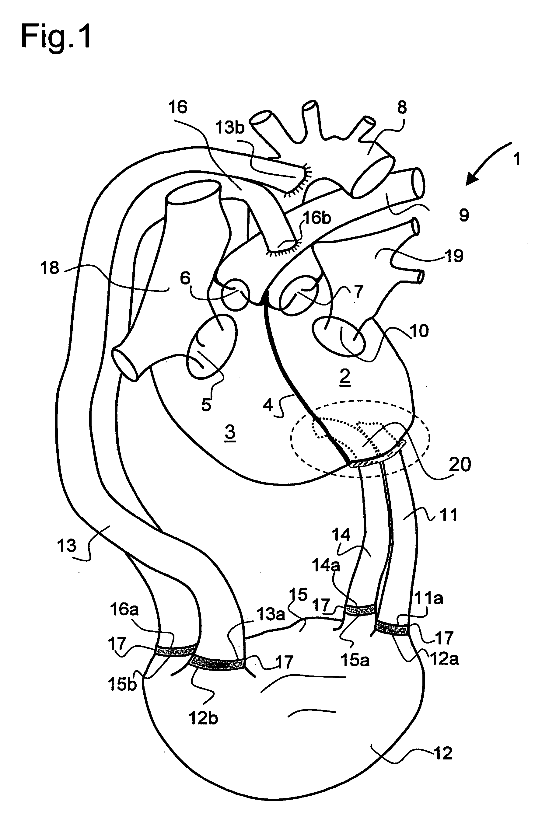
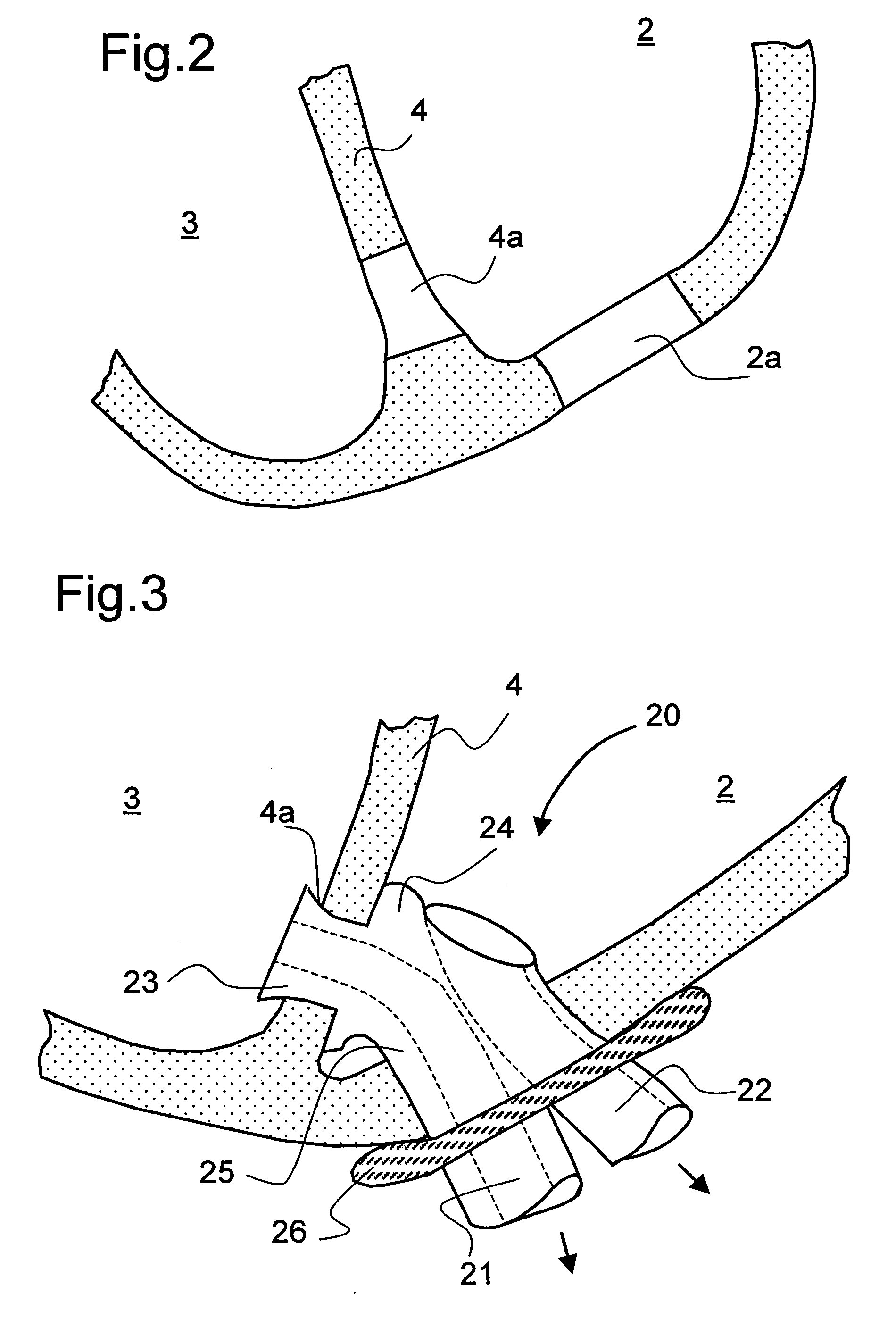
[0038] Referring now to FIG. 1 there is illustrated pronounced diagrammatically a heart identified in its entirety by the reference numeral 1, comprising a left atrium 19, a left ventricle 2 as well as a right atrium 18 and a right ventricle 3. The left ventricle 2 is separated from the right ventricle 3 by a septum 4 formed of strong heart muscle tissue.

[0039] Provided between the two atriums 18 and 19 and the corresponding ventricles 3 and 2 are valves in the form of the tricuspid valve 5 and mitral valve 10 respectively. Illustrated furthermore diagrammatically between the left ventricle 2 and aorta 8 is the aortic valve 7 as well as between the right ventricle 3 and the pulmonary artery 9 leading to the lung is the pulmonary valve 6.

[0040] Illustrated below the heart 1 diagrammatically is a dual-chamber pumping device as detailed in DE 102 17 635 A1 of which only the two chambers are indicated in the drawing greatly simplified and diagrammatically, namely a chamber 12 and a ch...


PUM


Abstract

For connecting a cardiac biventricular assist means including a dual-chamber pumping device, and an electrically powered compressor means provided between the two chambers (12, 15) a partially flexible one-part or multi-part adapter (20) is provided with two through-passageways (21, 22; 34, 35) each separate from the other, said adapter being securely held, on the one hand, in a port (4a) in the apical portion of the septum (4) and, on the other, in a port (2a) in / at the apex of the left ventricle (2) so that the through-passageway (22; 35) extending into the left ventricle (2) is connected directly or by means of a first flexible tube (11) to the inlet (12a) of the one chamber (12) and the other through-passageway (21; 34) extending into said right ventricle (3) is connected directly or by means of a second flexible tube (14) to the inlet (15a) of the other chamber (15).

Description

FIELD OF THE INVENTION [0001] The invention relates to a device for connecting a cardiac biventricular assist means including a dual-chamber pumping device, the chambers of which each comprise an inlet and an outlet including cardiac valve prostheses, the outlet of the one chamber being connected to the aorta and the outlet of the other chamber being connected to the pulmonary artery, and featuring an electrically powered compressor means provided between the two chambers. BACKGROUND OF THE INVENTION [0002] Cardiovascular diseases have since become the number one fatality in western industrial nations with ishemic heart disease and heart failure being the most frequent causes of death in Germany. Of a total of 2.7 million in in-patient treatment for cardiovascular diseases, roughly 15% die. [0003] Implantable mechanical ventricular assist devices (VAD) have been in use now clinically for some 15 years. This form of therapy mainly serves as a bridge to transplant when no donor organ ...

Claims


Application Information

Patent Timeline
22 Sep 2005
Publication
US20050209502A1
IPC
A61B17/00; A61B17/11; A61B17/115; A61F2/06; A61M60/183; A61M60/268; A61M60/861
CPC
A61B17/115; A61B2017/00252; A61M1/122; A61F2/064; A61M1/1008; A61B2017/1135; A61M60/894; A61M60/148
Inventors
SCHMID, THOMAS; SCHILLER, WOLFGANG