Ion beam irradiation apparatus and insulating spacer for the same

a technology insulating spacer, which is applied in the field of ion beam irradiation apparatus and insulating spacer for the same, can solve the problems of short circuit of grids, deterioration of insulating performance, and deterioration of insulating spacers, so as to reduce the amount of ions blocked by grids, improve ion utilization efficiency, and uniform milling rate

Inactive Publication Date: 2005-09-29
TDK CORPARATION
View PDF12 Cites 22 Cited by
  • Summary
  • Abstract
  • Description
  • Claims
  • Application Information

AI Technical Summary

Benefits of technology

[0035] According to the present invention, the insulating member is disposed on the surface of the grid adjacent to the plasma to generate a self-bias effect, thereby forming an ion sheath positively to control the plasma generation condition so that the ion density in the discharge space can be made uniform. Therefore, even if ions are extracted from all over the generated plasma evenly, the obtained ion quantity is substantially uniform throughout the ion extraction area. In other words, as compared to the prior art described before, the amount of the ions blocked by the grids is greatly reduced, and the utilization efficiency of ions can be enhanced. In addition, the amount of the ions blocked by the grids, or the ions that sputters the grids is reduced, so that inclusion of impurity elements into the ion beam from the grids can also be greatly reduced.
[0036] According to the present invention, a member made of an insulating material is locally inserted between grids to differentiate the electric capacitance between the grids locally. By selecting the insulating material appropriately or changing the thickness of this member to control the distance between the grids more finely, it is possible to partially change the energy (or the speed) of the ions. By virtue of this effect, it is possible to further correct, for example, the milling rate, which depends on the quantity of the extracted ions, to obtain a more uniform milling rate.
[0037] It is known that generally in the ion beam extraction apparatus of the above-described type, the grid intervals etc. change with an increase in the interior temperature of the apparatus or other conditions under operation, and therefore the quantity of the extracted ions, its distribution or other factors does not become stable until a significant time has elapsed. By inserting a member made of an insulating material between grids as taught by the present invention, the grid interval can be always kept constant, and it is possible to eliminate an preparatory operation for stabilizing the apparatus, which is required in conventional apparatuses.

Problems solved by technology

If the adhering material is electrically conductive, for example, the insulation performance of the insulating spacers is deteriorated with an increase in the adhering material, which can eventually lead to short-circuit of the grids.
Accordingly, for example in the case that a metal film is to be processed by a milling operation, the insulating performance is fast deteriorated by adhesion of the metal, and therefore it is necessary to perform the operations for preventing short-circuit at a significantly short cycle.
In these operations, when the adhering film is removed, the surface of the insulating spacer itself is subjected to the processing, and the surface will be broken or partly removed.
However, the provision of the annular projection results in an increase in the outer diameter of the spacer.
Therefore, the size of the annular projection is limited to sizes that do cause interference with the hole portions in the grid.
Typically, the aforementioned change returns to generally original state, but a small change that cannot be restored will accumulate with an increase in the number of times of running of the apparatus.
Consequently, there is a risk that operations such as milling cannot be performed appropriately unless the condition of the ion beam is minitored continuously to control the energy distribution by feedback.
Generally, ions extracted from a plasma inherits the ion distribution (or the ion density) in the plasma, and therefore the quantity of the extracted ions is not uniform depending on the extracted position.
However, alteration of the intervals of the grids or the distance between the grids and the article to be processed does not result in improvement in the basic distribution.
In addition, the alteration of the plasma condition has not been positively tried so far since it is difficult to be monitored.
Consequently, there are a large amount of ions that are blocked by the grids and do not contribute to milling or other operations.
In addition, the ions blocked by the grids sputter the grid surface, which can be a cause of impurities contained in the ion beam.
Therefore, in the case that ion density distribution is extremely inhomogeneous due to some conditions such as the gas type or the discharge pressure, it is considered that there may occur such a situation that the uniformization per se is difficult to be achieved or that the extracted ion quantity of the portion standardized for the uniformization is too small to be practically used.
Accordingly, there is the possibility that the extraction of the ion can be effected only in limited conditions, and versatility of the apparatus as such may be restricted.

Method used


Image

  • Ion beam irradiation apparatus and insulating spacer for the same
  • Ion beam irradiation apparatus and insulating spacer for the same
  • Ion beam irradiation apparatus and insulating spacer for the same

Examples


first embodiment

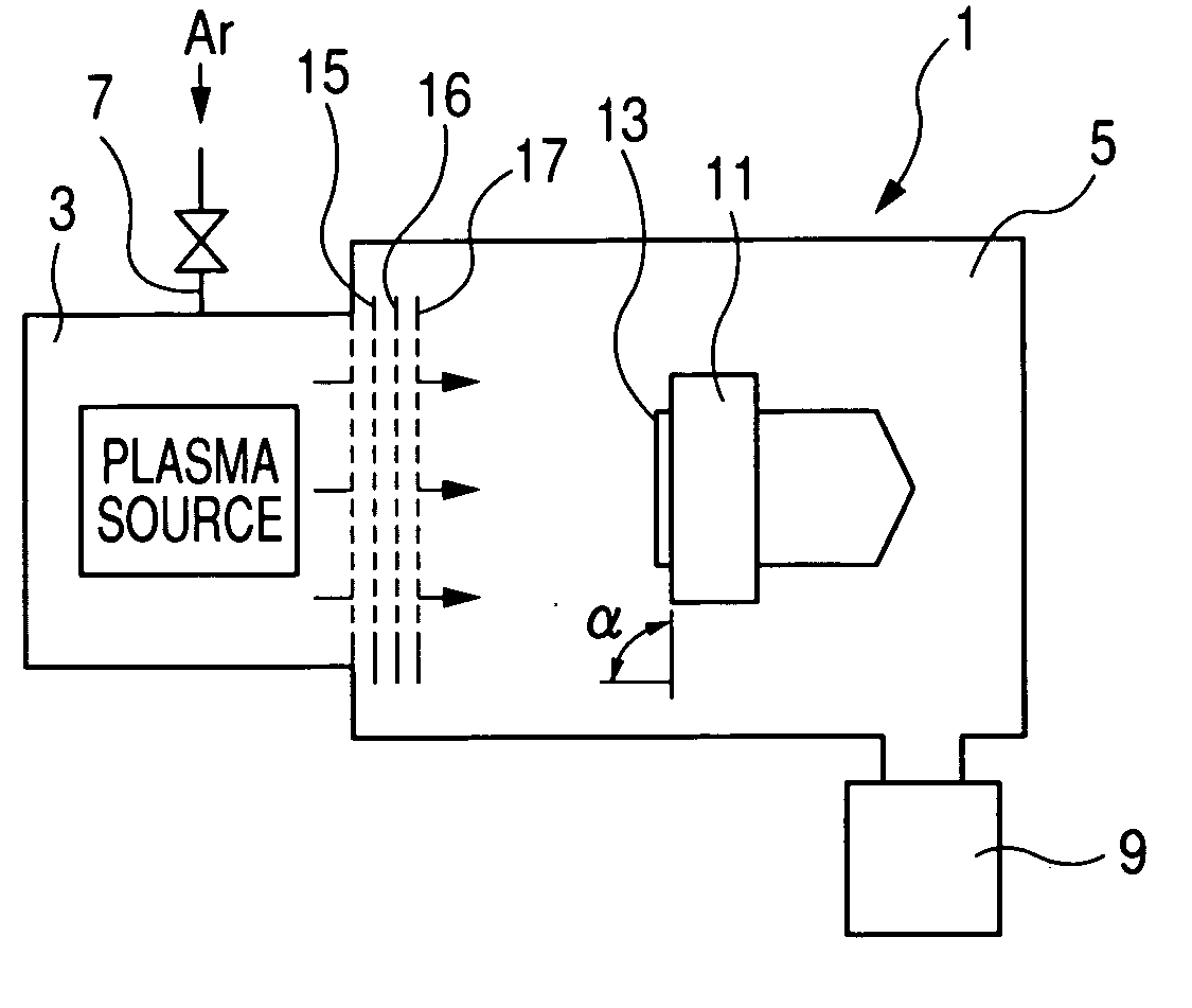
[0052] In the following, embodiments of the present invention will be described with reference to the drawings. FIG. 1 schematically shows the outline of an ion milling apparatus 1 equipped with,as an ion source, an ion beam irradiation apparatus having insulating spacers according the present invention. The apparatus 1 is composed of two chambers, that is, a plasma generation chamber 3 and a process chamber 5. In the plasma generation chamber 3 in this embodiment, for example argon gas is supplied to the plasma generation chamber through a gas supply system 7 as the gas to be subjected to plasma generation. There are various methods of generating a plasma such as the Kaufmann type, the bucket type, the ICP type and the ECR type, and any of these method may be employed. In this embodiment, the plasma is generated by an IPC type system in which the possibility of inclusion of impurity elements in the ion beam is relatively low and the structure of the apparatus is simple. The process...

second embodiment

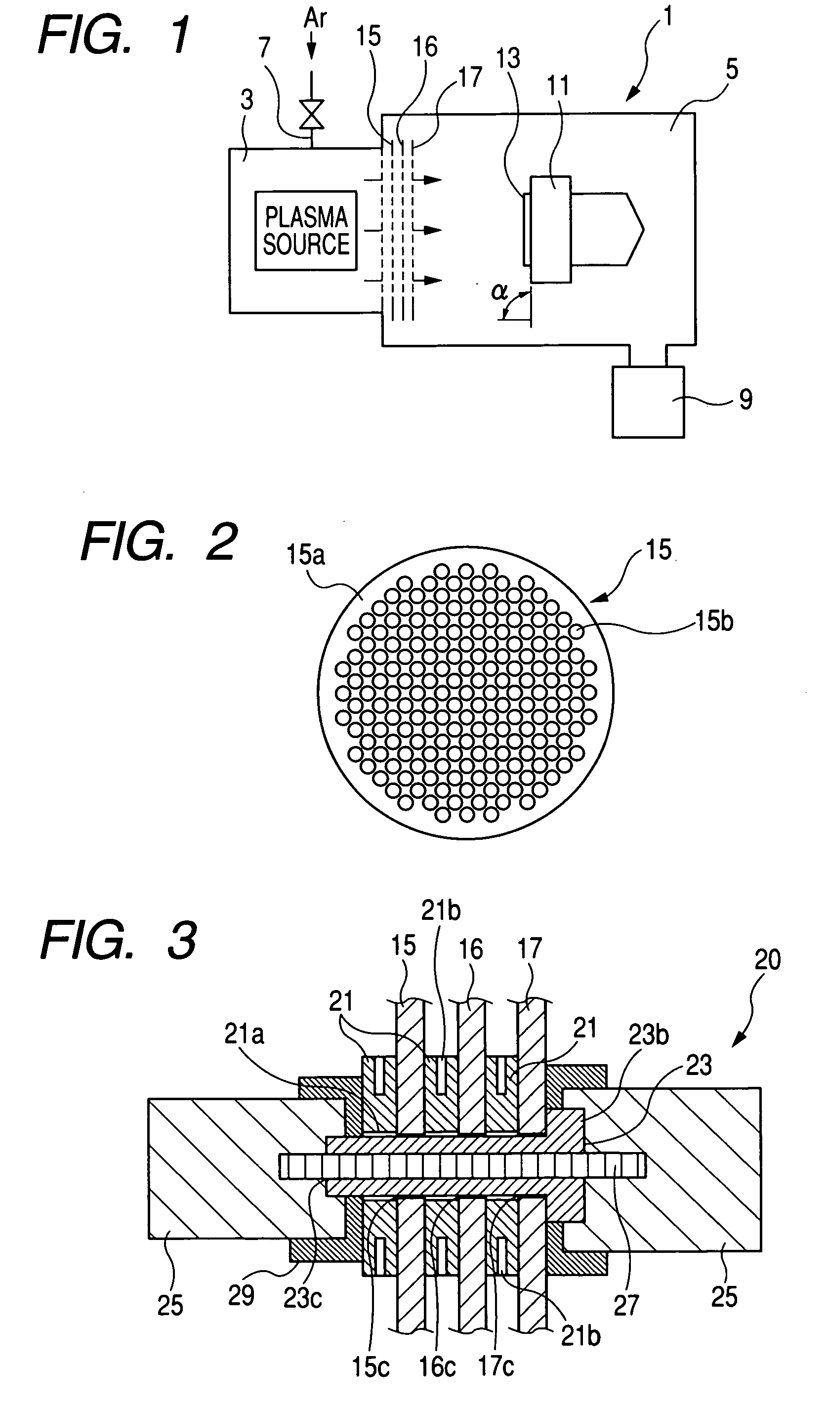
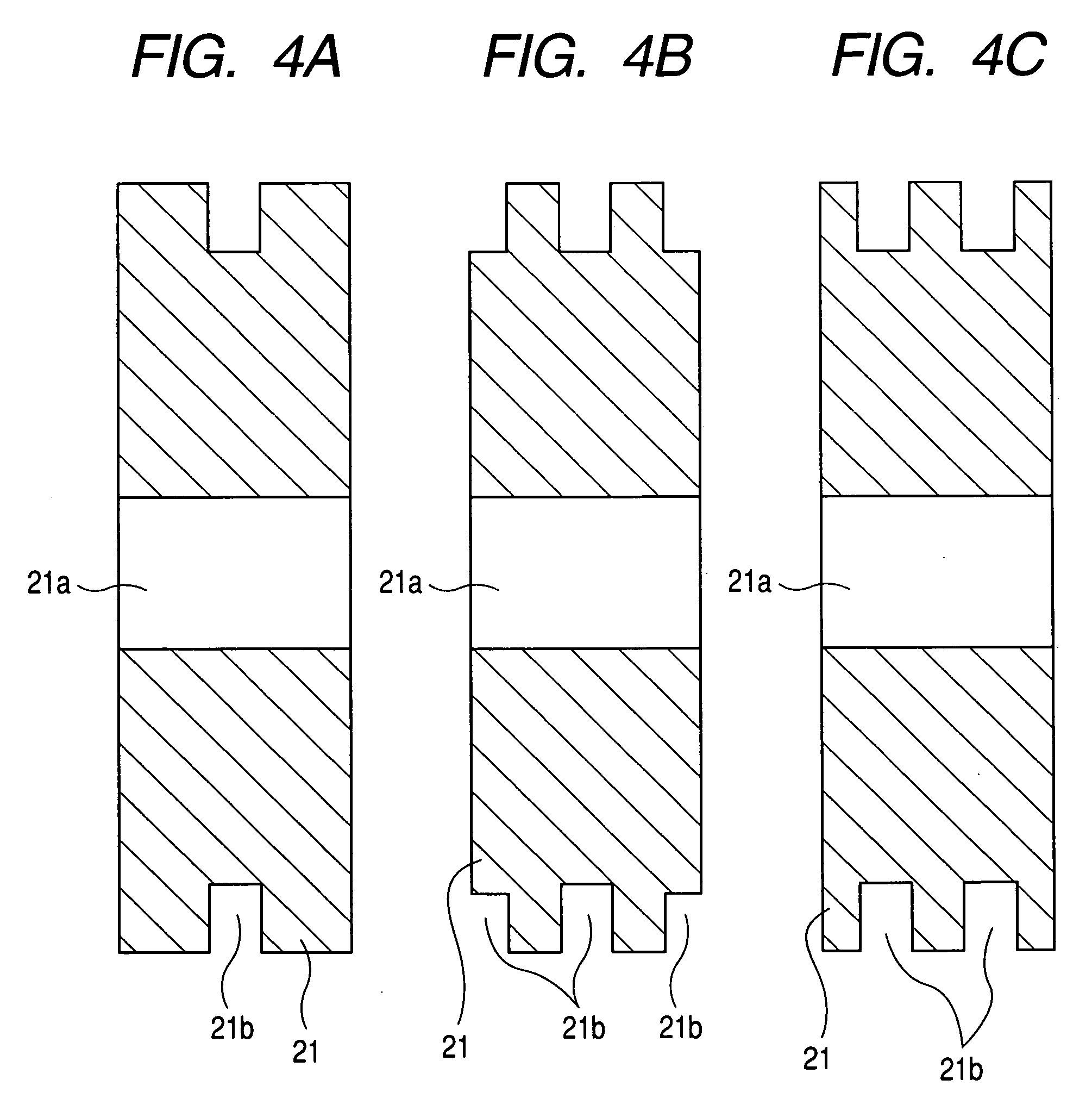
[0066]FIG. 7 schematically shows the structure of a fixing apparatus for fixing the first to third grids 15, 16, 17 at predetermined intervals and fixing insulating spacers between the grids. The fixing apparatus 120 is composed of insulating spacers 121, an insulating member 23, insulating caps 25, a screw rod 27 and grooved washers 29. The insulating spacer 121 is a disk like member with parallel end faces made of an insulating material such as alumina. The insulating spacer 121 has a through hole 121a with a predetermined diameter that passes through its top and bottom surfaces, formed at its center. The thickness of the disk corresponds to the distance between the grids. The insulating member 23 is a substantially cylindrical member including a shaft portion 23a having an outer diameter that can pass through the through hole 121a of the insulating spacer 121 and an enlarged diameter portion 23b having an enlarged diameter formed at one end thereof. The insulating member 23 has ...


PUM


Abstract

The frequency of replacement of an insulating spacer disposed between grids of an ion beam irradiation apparatus is to be reduced. In addition, the intervals of the multiple grids in the ion beam irradiation apparatus are to be kept constant. To achieve these objects, in a so-called insulating spacer provided for maintaining insulation between the grids, a groove portion having a bottom onto which sputtered materials are hard to adhere is provided on the central portion of the side surface of the insulating spacer all along its circumference.

Description

BACKGROUND OF THE INVENTION [0001] 1. Field of the Invention [0002] The present invention relates to an ion beam irradiation apparatus for extracting an ion beam from a plasma generated in a chamber through a grid to which a predetermined voltage is applied to emit an ion beam to a predetermined direction. More particularly, the present invention relates, for example, to an ion milling apparatus for processing a surface of an article to be processed using the extracted ion beam, an ion implantation apparatus for implanting ions into a film using the extracted ion beam, an ion beam deposition apparatus for forming a film, and an insulating member used in these apparatuses as a spacer in fixing a grid. [0003] 2. Related Background Art [0004] For example, the milling apparatus utilizing an ion beam uses a plasma generated in a chamber as an ion source. The apparatus extracts ions from the ion source using a plurality of grids to which a DC voltage is applied to accelerate the ions in a...

Claims


Application Information

Patent Timeline
Patent Type & Authority Applications(United States)
IPC IPC(8): A61N5/00G21K5/10H01J27/02H01J37/08H01J37/30
CPCG21K5/10H01J2237/3151H01J37/08
Inventor ITO, KATSUMIMAEKAWA, KAZUYATAKEUCHI, ETSUOYAJIMA, NOBUOSATO, JUNICHI
Owner TDK CORPARATION
Why Eureka
Try Eureka