

Fluorescent material and light-emitting device
a fluorescent material and light-emitting device technology, applied in the direction of discharge tube luminescent screen, discharge tube/lamp details, luminescent compositions, etc., can solve the problems of blackening the appearance of the afterglow, significantly impairing the afterglow luminosity, and relatively long afterglow period. achieve the effect of wide chromatic range and high luminosity
- Summary
- Abstract
- Description
- Claims
- Application Information
AI Technical Summary
Benefits of technology
Problems solved by technology
Method used
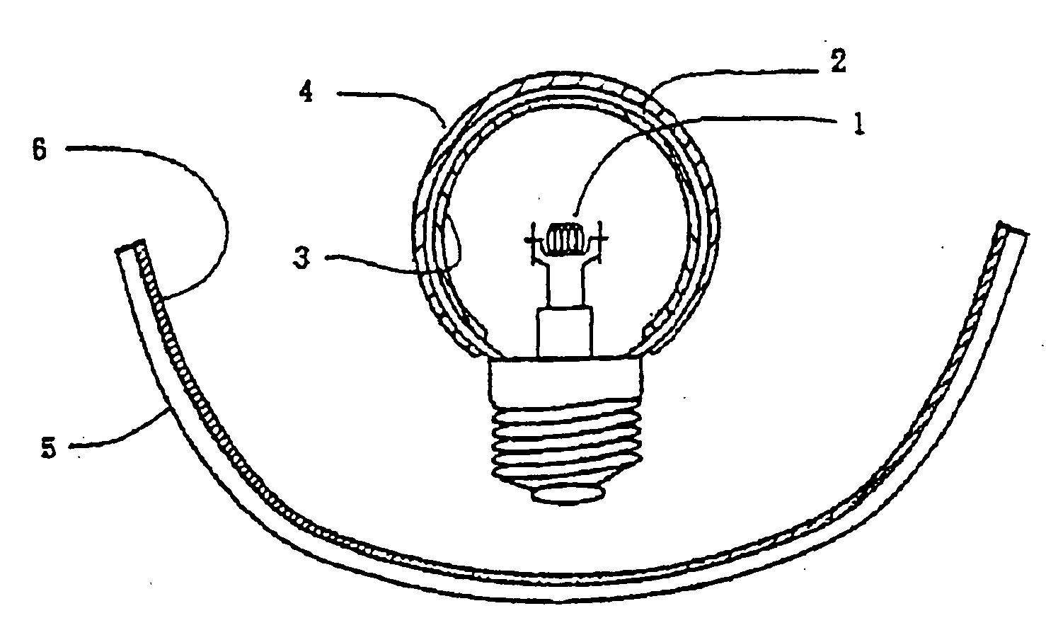
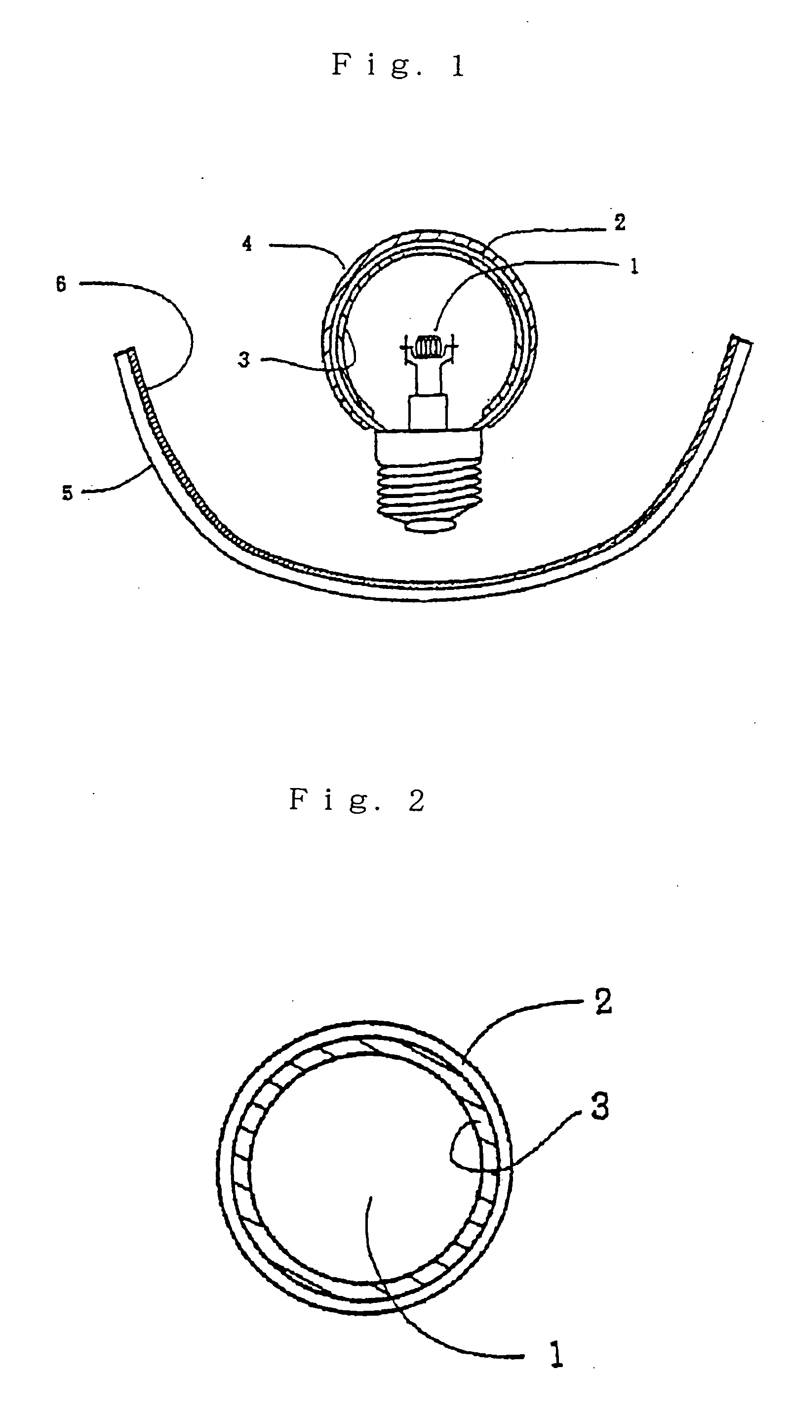
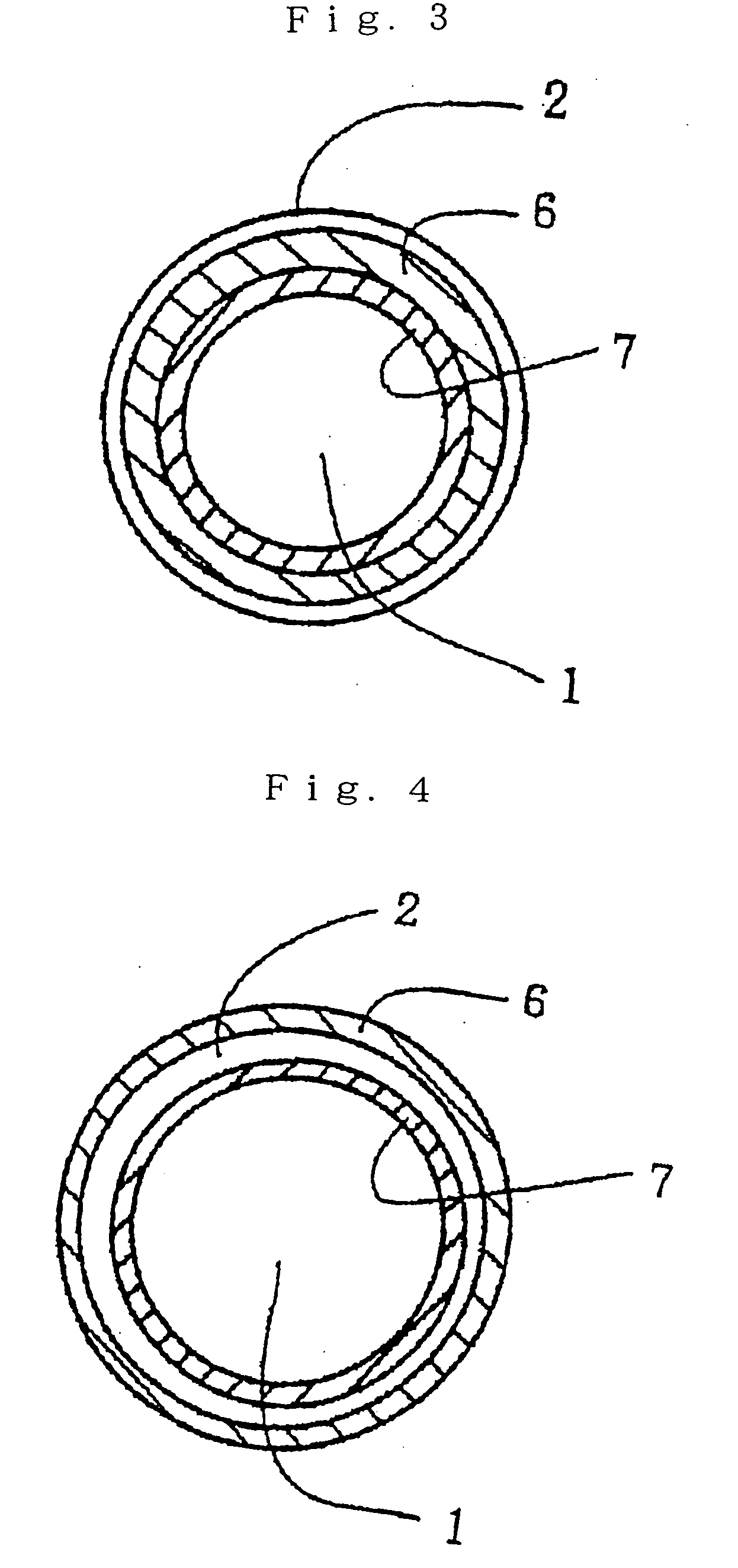
Image

Examples
example 1
[0335] 144.7 g of SrCO3, 178.4 g of Al2O3, 1.8 g of Eu2O3, and 1.9 g of Dy2O3 were measured and then sufficiently mixed in a ball mill. The mixed ingredients were introduced into an alumina crucible and calcined in a reducing atmosphere of N2 and H2 at 1200 to 1400° C. for about 3 hours. The calcined product thus obtained was pulverized, dispersed, sieved, separated, water-washed, and dried, thereby yielding a first phosphor.
[0336] The first phosphor had an Sr:Eu:Dy composition of 0.98:0.01:0.01, and an (Sr / Eu / Dy):Al:O composition of 4:14:25.
[0337] Next, 12.9 g of Y2O3, 31.0 g of Gd2O3, 2.6 g of CeO2, and 51.0 g of Al2O3 were measured and then sufficiently mixed in a ball mill. The mixed ingredients were introduced into an alumina crucible and calcined in a reducing atmosphere of N2 and H2 at 1300 to 1500° C. for about 3 hours. The calcined product thus obtained was pulverized, dispersed, sieved, separated, water-washed, and dried, thereby yielding a second phosphor.
[0338] The se...
example 2
[0340] The first and second phosphors as obtained in Example 1 were uniformly mixed in a weight ratio of 4 to 6, thereby yielding a fluorescent material of the invention.
example 3
[0341] 98.1 g of CaCO3, 101.9 g of Al2O3, 1.8 g of Eu2O3, and 1.7 g of Nd2O3 were measured and then sufficiently mixed in a ball mill. The mixed ingredients were introduced into an alumina crucible and calcined in a reducing atmosphere of N2 and H2 at 1200 to 1400° C. for about 3 hours. The calcined product thus obtained was pulverized, dispersed, sieved, separated, water-washed, and dried, thereby yielding a first phosphor.
[0342] The first phosphor had a Ca:Eu:Nd:Al:O composition of 0.98:0.01:0.01:2:4.
[0343] Next, 30.48 g of Y2O3, 2.7 g of Gd2O3, 2.6 g of CeO2, and 51.0 g of Al2O3 were measured and then sufficiently mixed in a ball mill. The mixed ingredients were introduced into an alumina crucible and calcined in a reducing atmosphere of N2 and H2 at 1300 to 1500° C. for about 3 hours. The calcined product thus obtained was pulverized, dispersed, sieved, separated, water-washed, and dried, thereby yielding a second phosphor.
[0344] The second phosphor had a Y:Gd:Ce composition ...
PUM
| Property | Measurement | Unit |
|---|---|---|
| thickness | aaaaa | aaaaa |
| wavelength | aaaaa | aaaaa |
| temperatures | aaaaa | aaaaa |
Abstract
Description
Claims
Application Information