
Manufacturing method of ink-jet head

a manufacturing method and ink-jet head technology, applied in the field of ink-jet head manufacturing method, can solve the problems of reducing image quality, affecting production efficiency, and affecting the quality of ink drop, so as to prevent the deterioration of piezoelectric body properties, reduce the time of laser irradiation, and improve the effect of production efficiency

Inactive Publication Date: 2005-09-29
KONICA MINOLTA INC
View PDF6 Cites 0 Cited by
  • Summary
  • Abstract
  • Description
  • Claims
  • Application Information

AI Technical Summary

Benefits of technology

[0018] According to the description set forth in this structure 1, the invention is a method in which a plating film thinner than the thickness required for electrodes is previously formed, and after the thin plating film deposited on the portions for which no plating is necessary is removed by a laser beam, plating processing is done over again. In doing plating over again, by the self-catalyzing function of the thin plating film remaining not removed, further plating film is deposited on the places where the thin plating film remains, to form electrodes and connection electrodes. Because a plating film which is thinner than that to be removed in conventional methods is removed by a laser beam, only a small power for a laser beam is necessary, the deterioration of the property of the piezoelectric body is prevented, electrode formation with a good production efficiency can be performed, and generation of defective products in the manufacturing process is suppressed, which makes it possible to manufacture a high-precision ink jet print head, whose miniaturization is in progress, at a low cost.
[0021] In the invention of structure 3, after a catalyst layer is adsorbed over the whole surface of the channel plate, the catalyst layer on the places for which no plating is necessary is removed by a laser beam, and after that, by applying electroless plating, a plating film is deposited on the places where the catalyst layer remains, to form electrodes and connection electrodes. Because only it is necessary to remove adsorbed catalyst layer having a weight of ng order or to inactivate it by thermal oxidization, only an extremely small power is necessary for the laser, the deterioration of the property of the piezoelectric body is prevented, electrode formation with a good production efficiency can be performed, and generation of defective products in the manufacturing process is suppressed, which makes it possible to manufacture a high-precision ink jet print head, whose miniaturization is in progress, at a low cost.
[0023] According to the invention set forth in this structure 4, after a plating film is formed on the inner walls of a plurality of tube-shaped channels formed on a head tip and the outer peripheral surface by applying plating processing to the inner wall surface, the plating film on specified portions of the outer peripheral surface is removed by a laser beam, to form electrodes in the channels and connection electrodes on the outer peripheral surface of the head tip. Because the top plate is bonded before plating, it is unnecessary to irradiate the roof portion of the partition walls of the grooves by a laser beam; therefore, laser irradiation time becomes shorter. Because the partition walls of the grooves, which are concerned with the jetting of ink drops, are not irradiated by a laser beam, and only it is necessary to irradiate the outer surface of the head tip, which does not influence the jetting of ink so much, deterioration caused by heat is not produced so much, and plating of only one time is necessary. Thus, the deterioration of the property of the piezoelectric body is prevented, electrode formation with a good production efficiency can be performed, and generation of defective products in the manufacturing process is suppressed, which makes it possible to manufacture a high-precision ink jet head, whose miniaturization is in progress, at a low cost.
[0024] In the invention of structure 5, after a thin plating film is formed on the inner walls of a plurality of tube-shaped channels formed on a head tip and on the outer peripheral surface, the plating film on specified portions of the outer peripheral surface is removed by a laser beam, and electroless plating is carried out again, to form electrodes in said channels and connection electrodes on the outer peripheral surface of the head tip. Because the top plate is bonded before plating, it is unnecessary to irradiate the roof portion of the partition walls of the grooves by a laser beam; that is, it is not required to irradiate the portions which are directly concerned with ink jetting by a laser beam. The deterioration of the property of the piezoelectric body is prevented, and generation of defective products in the manufacturing process is suppressed, which makes it possible to manufacture a high-precision ink jet head, whose miniaturization is in progress, at a low cost.

Problems solved by technology

However, because these shallow groove portion and uncut portion is not scarcely deformed by the application of an electric voltage, they cannot contribute to the jetting of ink drops.
As described in the above, if the speed of jetted ink drops varies from one channel to another channel depending on the print pattern, fluctuation of the landing position of the ink drops landing on a medium which is moving at a constant speed with respect to the print head is produced, which lowers image quality remarkably.
That is, the structure of a conventional print head is not suitable for a head to have a high image quality, a high speed, and a high density.
However, because it has neither shallow groove portions nor uncut portions, there no space to form connection electrodes.
The present pattern formation technology employing a photosensitive resist can form a planar pattern, but cannot form a cubic pattern.
However, if straight grooves are formed, a conventional method of patterning by means of a photosensitive resist cannot be used, because connection electrodes must be formed in a cubic way.
However, because the thickness of the head is as thin as 2 to 10 mm, it is difficult to form a minute pattern by coating a photosensitive resist in this portion to be exposed and developed.
In manufacturing piezoelectric elements, even though exact holes are formed in a green sheet, when it is sintered, expansion and contraction occurs remarkably, which makes it difficult to form holes having a diameter of several tens μm with an accuracy of several μm.
Further, when grooves are worked with their position adjusted to coincide with these via holes, it is produced a problem that the positions are deviated for example.
However, if the film thickness is large, repeated irradiation is necessary, and there is a possible risk of the deterioration of the underlying piezoelectric element which is weak against heat.
Up to now, for example, according to the publications of the unexamined patent applications 2000-168094 and H8-300667, after the whole of a print head is plated in an electroless way, unnecessary portions of the plating layer are removed by a laser beam; however, because the plated metal, for example, nickel is a very hard metal, a large laser power is necessary, and there is a possible risk of the underlying piezoelectric element being overheated.

Method used


Image

  • Manufacturing method of ink-jet head
  • Manufacturing method of ink-jet head
  • Manufacturing method of ink-jet head

Examples


Embodiment Construction

[0043] In the following, the embodiment of a method of manufacturing an ink jet print head of the present invention will be explained on the basis of the drawings, but the present invention is not limited to this embodiment.

[0044] To state the first example of the present invention, in electroless plating which is applied to a head substrate having straight grooves formed, when an extremely thin plating layer having a thickness of 0.5 μm for example has been produced, it is taken out from the plating bath and is washed by water, and then, as shown in FIG. 15(a) and FIG. 15(b), a laser beam is applied to linear areas extending from the roof of the side wall of grooves, through the rear end surface, to the bottom surface of the head, to remove the plated metal on them. Because the amount of metal to evaporate is very small, the temperature of the piezoelectric substrate is not so much raised. After washing, it is put into the plating bath again; then, plating layer begins to grow aga...


PUM

PropertyMeasurementUnit
thicknessaaaaaaaaaa
thicknessaaaaaaaaaa
thicknessaaaaaaaaaa

Abstract

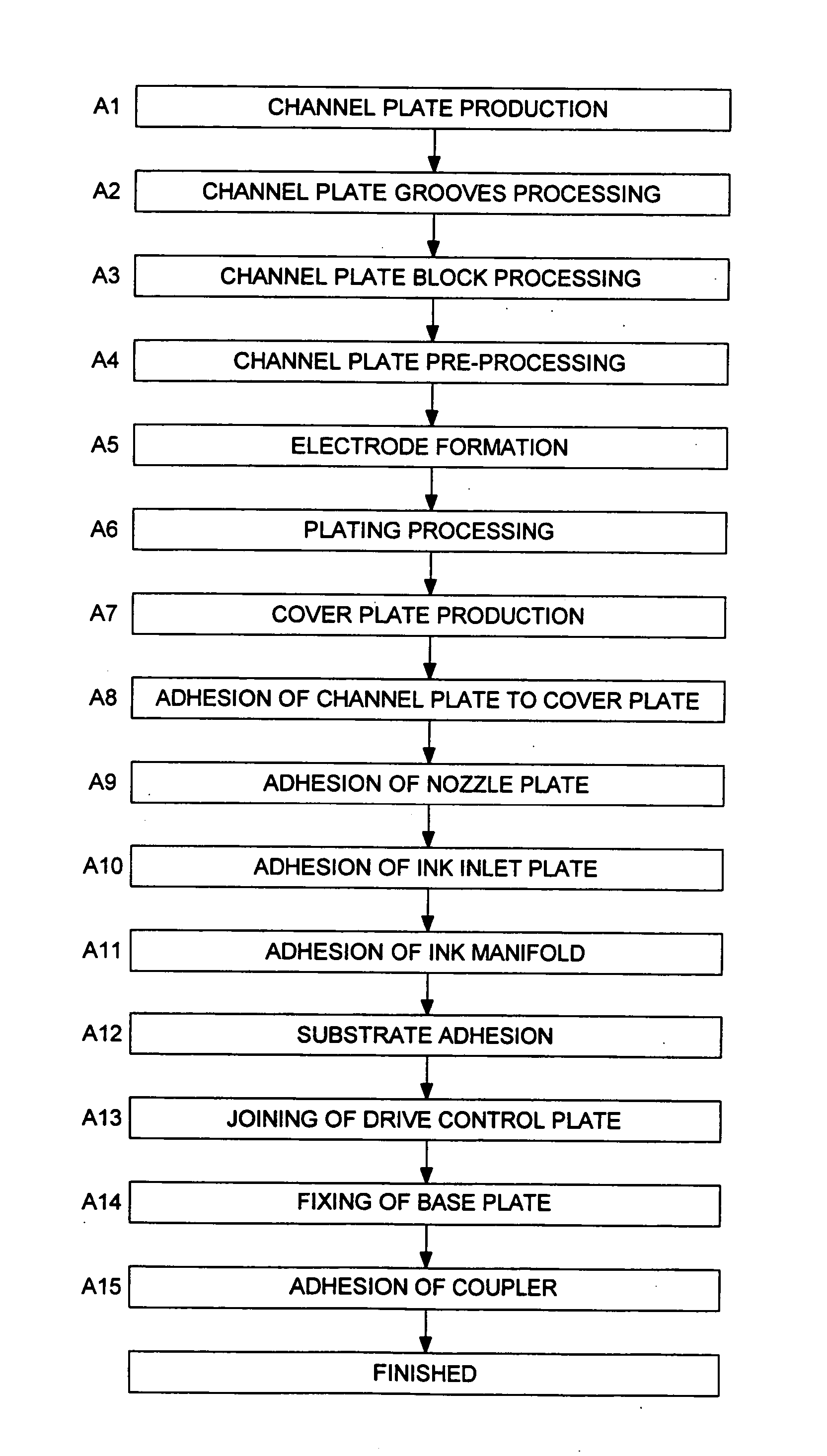
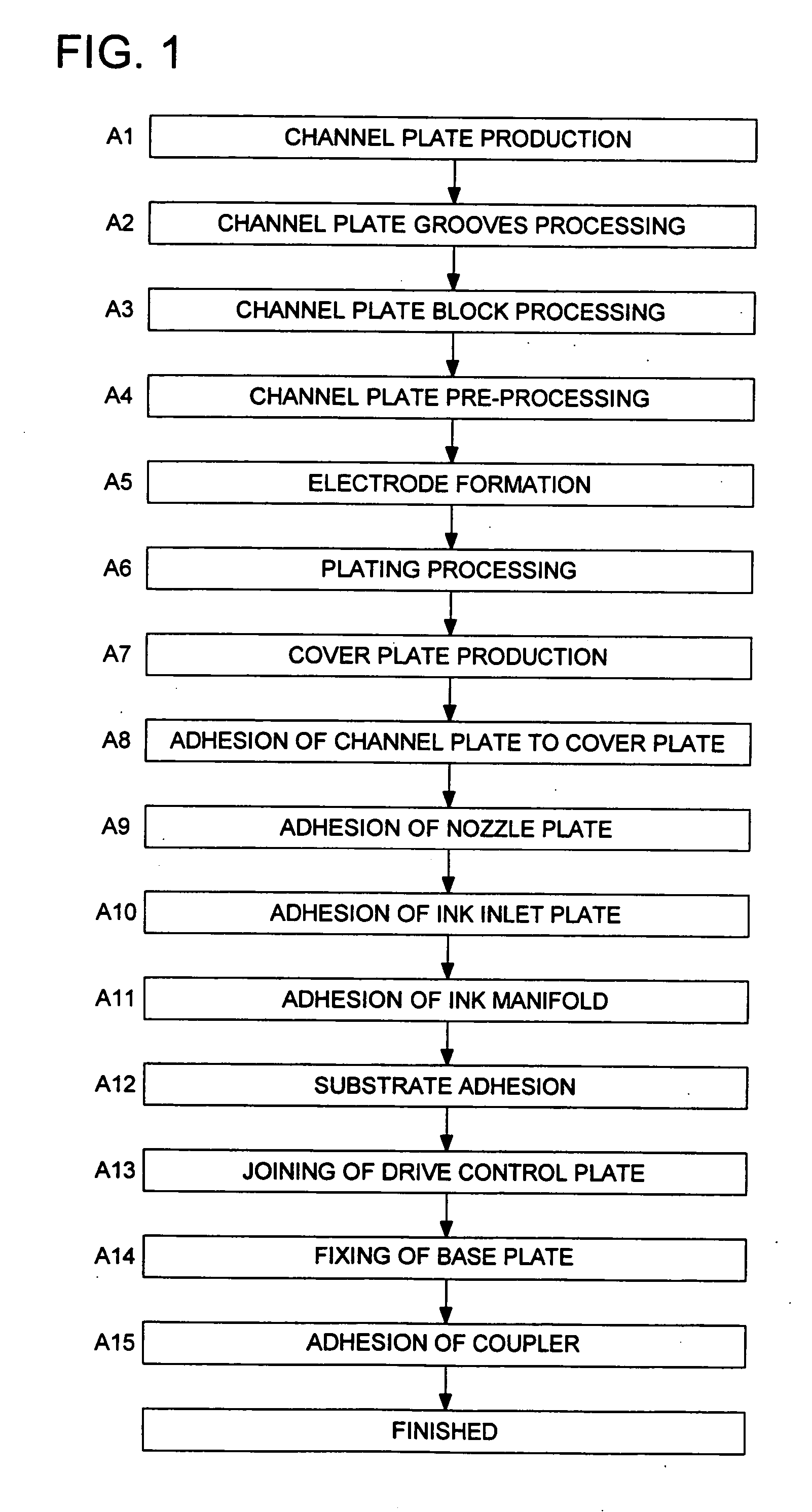
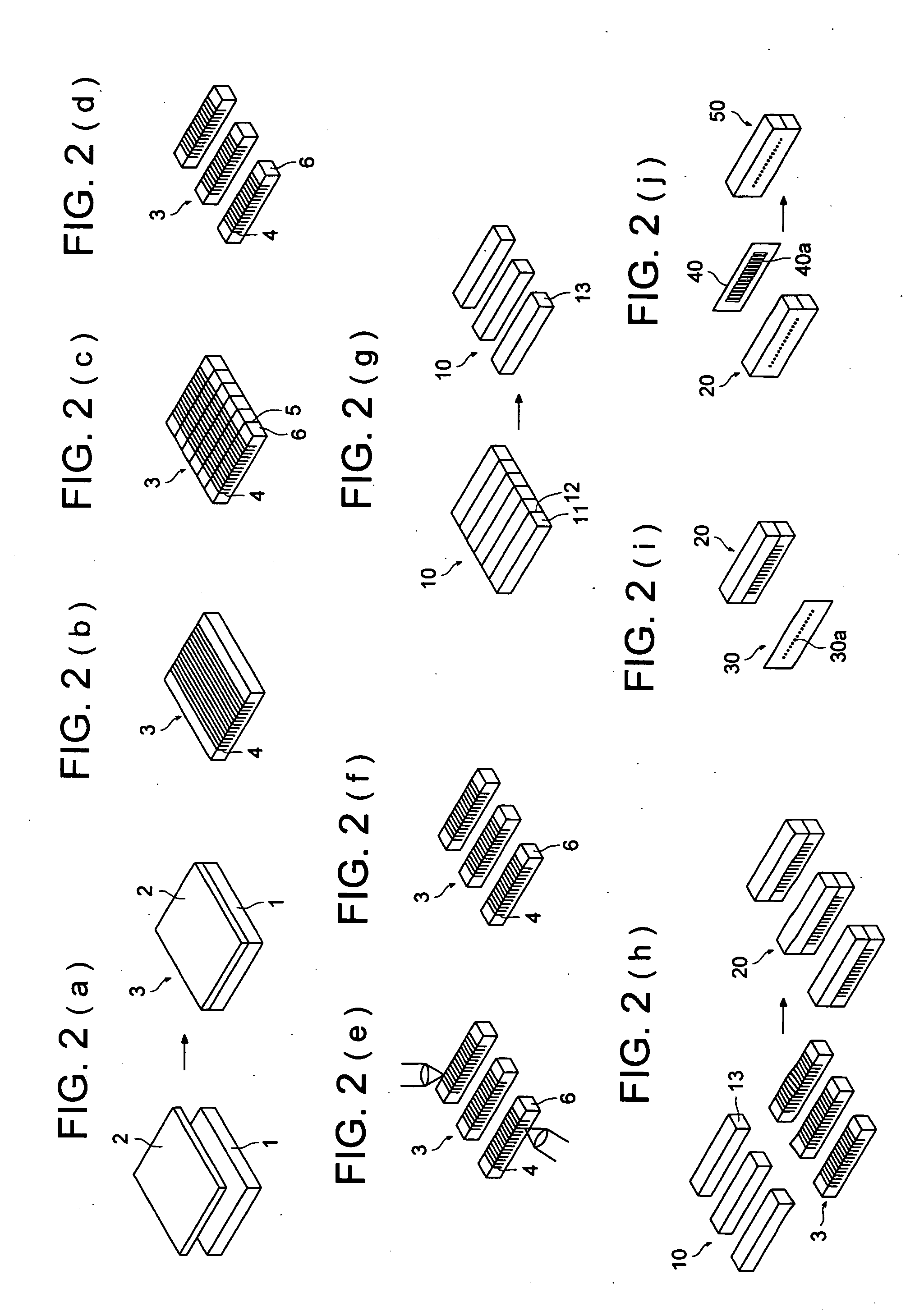
In a method for manufacturing an ink-jet print head in which ink channels are formed on a member including a piezoelectric body, and ink is jetted from each of the ink channels by applying a voltage to electrodes provided on the piezoelectric body according to each of the ink channels, thereby driving the piezoelectric body, the method includes the steps of: plating a surface of a channel plate having a plurality of grooves for the ink channels thereby forming a thin-film plating layer which is thinner than a desired thickness; removing a part of the thin-film plating layer by a laser beam; and plating again the channel plate thereby forming an additional plating layer on the thin-film plating which has not been removed by the laser beam, and thereby forming the electrodes of the desired thickness.

Description

[0001] This is a Continuation Application of application Ser. No. 10 / 021,216, filed Dec. 12, 2001, now pending, which is hereby incorporated in its entirety herein by this reference.BACKGROUND OF THE INVENTION [0002] The present invention relates to a method of manufacturing an ink jet print head of a shear mode type using a piezoelectric element and having a high image quality, a high speed, and a high density. An ink jet print head of a shear mode type has ink channels formed in a polarized piezoelectric substrate by cutting and grinding, and has electrodes formed on the partition walls of the channel grooves; it jets ink drops when an electric field is applied to these electrodes to cause the partition walls of the grooves to be deformed to become dog-legged shape by a shearing force, to apply a pressure to ink in the grooves. For this ink jet print head, electrodes in the grooves and connection electrodes outside the grooves which transmit a signal to the electrodes are necessar...

Claims


Application Information

Patent Timeline
Patent Type & Authority Applications(United States)
IPC IPC(8): B41J2/16H05K3/02
CPCB41J2/1609B41J2/1634Y10T29/49401H05K3/027B41J2/1643
Inventor KIKUGAWA, SHOZOYAMADA, MINORUAKANABE, YUICHIITO, TAKESHIOKUNO, TETSUO
Owner KONICA MINOLTA INC
Learn More