Fuel cell system and method of discontinuing same
- Summary
- Abstract
- Description
- Claims
- Application Information
AI Technical Summary
Benefits of technology
Problems solved by technology
Method used
Image

Examples
first embodiment
[0022] a. First Embodiment
[0023] An embodiment of the present invention is described with reference to the accompanying drawings. Description is given of a fuel cell system mounted on a vehicle (not shown), for example.
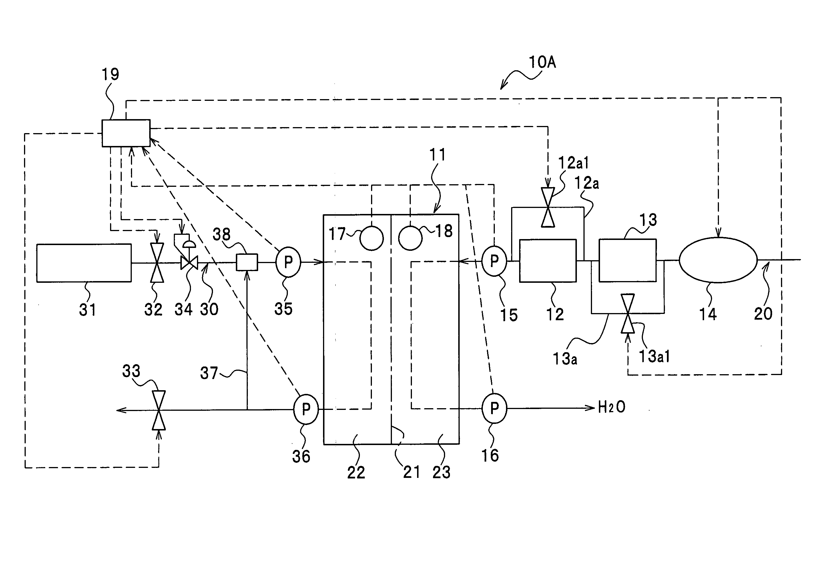
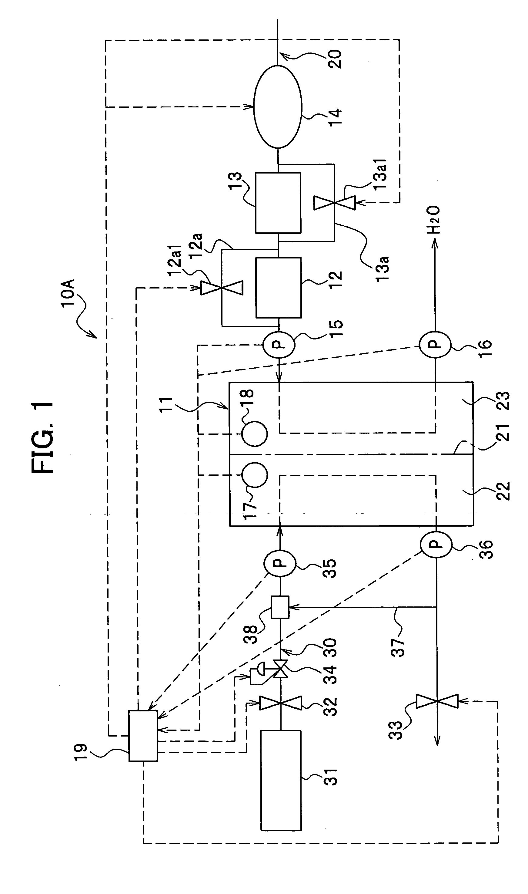
[0024] As shown in FIG. 1, a fuel cell system 10A includes a cathode passage 20 and an anode passage 30. The cathode passage 20 supplies air (reactive gas) as an oxidant and the anode passage 30 supplies a hydrogen gas as a fuel to a fuel cell 11, respectively.
[0025] A humidifier (humidifying device) 12, an intercooler (cooling device) 13 and a supercharger (gas supply device) 14 are each connected with the cathode passage 20. The humidifier 12, the intercooler 13 and the supercharger 14 are connected to each other in series in that order relative to a cathode inlet of the fuel cell 11. The intercooler 13 cools down a compressed air to a predetermined temperature, whose temperature has risen as a result of undergoing adiabatic compression conducted by the supercharg...
second embodiment
[0047] b. Second Embodiment
[0048] As shown in FIG. 3, a fuel cell system 10B according to a second embodiment generally has the same structure as that of a fuel cell system 10A according to the first embodiment except for first and second three-way valves 12a2 and 13a2 replacing first and second bypass valves 12a1 and 13a1, respectively. The first three-way valve 12a2 is located at a junction of first bypass passage 12a and a cathode passage 20 near an inlet of a humidifier 12. The second three-way valve 13a2 is located at a junction of second bypass passage 13a and the cathode passage 20 near an inlet of an intercooler 13. It is assumed in the second embodiment that the three-way valves 12a2 and 13a2 are able to select a direction of flow but are not able to control flow rate. Alternatively, it may be possible to select another type of valves capable of controlling flow rate. Description will not be repeated for items which are the same as those of the first embodiment, bearing the...
third embodiment
[0051] c. Third Embodiment
[0052] As shown in FIG. 5, a fuel cell 10C according to a third embodiment has a scavenging gas device 25, which is charged with a gas dedicated for scavenging a fuel cell 11. In this embodiment, the dedicated gas is provided for scavenging instead of a reactive gas used for chemical reaction as described in the first and second embodiments. The scavenging device 25 is charged with a highly pressurized inert gas such as a nitrogen gas, for example.
[0053] As shown in FIG. 5, passages 26 and 27 are connected to the scavenging gas device 25 so as to supply a scavenging gas to a cathode passage 20 and an anode passage 30, respectively. A junction of the passage 26 and the cathode passage 20 is located between an intercooler 13 and a supercharger 14. A junction of the passage 27 and the anode passage 30 is located near an anode inlet of a fuel cell 11. The passages 26 and 27 have respective valves 26a and 27a for controlling a flow rate of the scavenging gas, w...
PUM
 Abstract
Description
Claims
Application Information
PatSnap Eureka turns technology decisions into work you can execute. Powered by our Innovation Knowledge Graph, it runs expert workflows across engineering, life sciences, materials and intellectual property. Get your review-ready output in minutes.


