
Method for ignition of an oil burner and electronic ignition circuitry for oil burners

Inactive Publication Date: 2005-09-29
DANFOSS AS
View PDF6 Cites 2 Cited by
  • Summary
  • Abstract
  • Description
  • Claims
  • Application Information

AI Technical Summary

Benefits of technology

[0017] By the use of the method or the electronic ignition circuitry of the present invention, the frequency with which the ignition sparks occur in an oil burner may efficiently be de-tuned or de-correlated from the natural resonance frequency of the oil burner system, thereby preventing the unwanted resonance noise.
[0047] This has the advantage that the temperature control may be integrated in the ignition circuitry. This again has the advantage that immediately as the circuitry heats up less power is dissipated. Thus, allowing a longer operation duty cycle of the electronic ignition circuitry compared to the prior art circuit.

Problems solved by technology

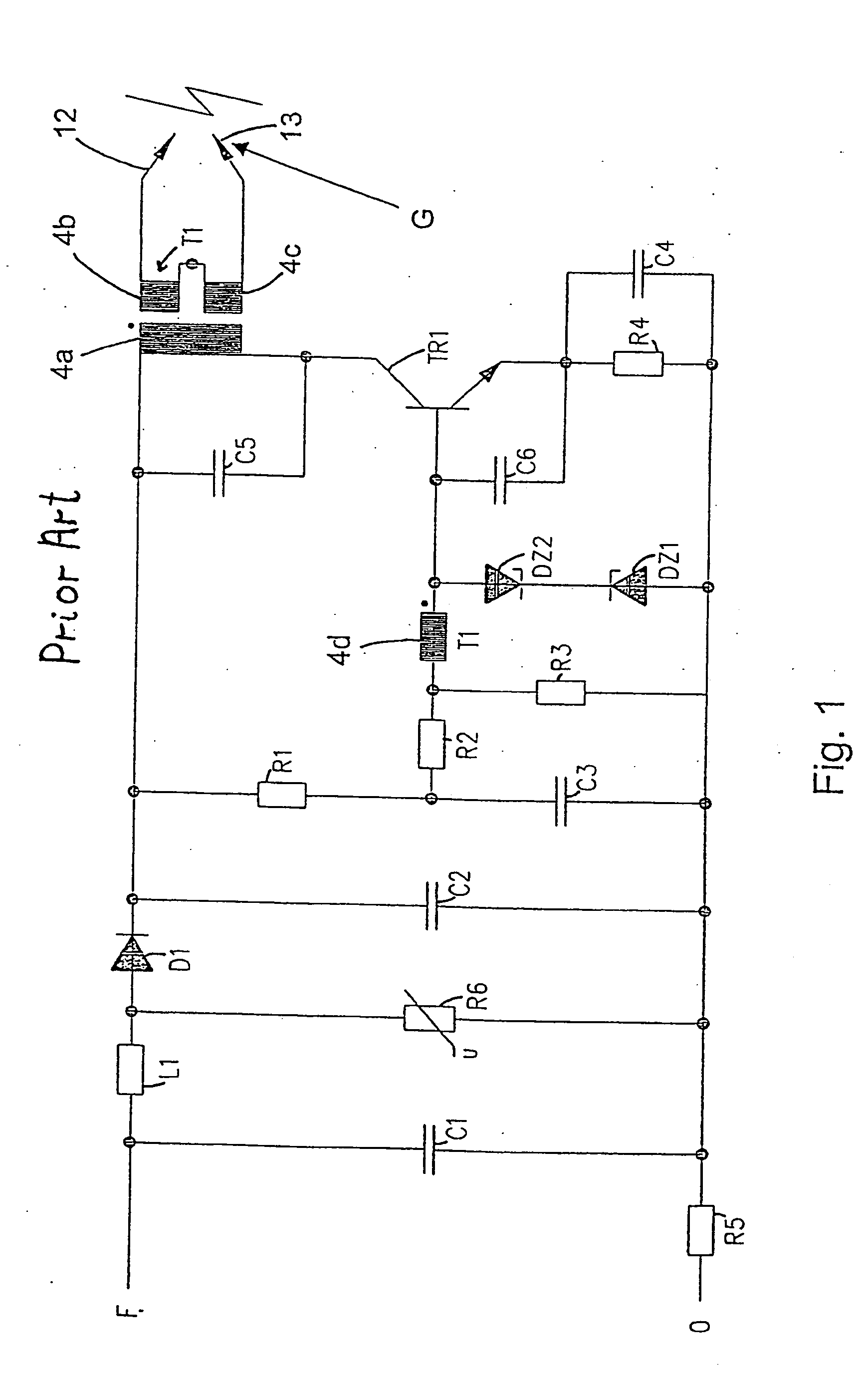
Though a prior art ignition unit with the above circuit has worked well over a number of years, it has been known that under certain circumstances acoustical resonance problems related to the ignition of the oil in the burner system occur.
These problems have been increasing over recent years.
These acoustical problems occur in situations where the combustion has reached a self-sustaining state.
If, in the above situation, it happens that these 50 Hz pressure pulses coincide with a resonance frequency of the system, e.g. of the Helmholz resonator formed mainly by the combustion chamber and the exhaust duct or of individual parts of the system, the system may be unacceptably noisy producing an annoying howling whenever ignition occur during combustion.
Since the frequency at which resonance occurs often relate to the Helmholz resonator formed by the combustion chamber and the exhaust duct, the situations where this happens may not easily be predicted, as oil burner systems are often so as to include exhaust ducts in the form of existing chimneys.
Thus, the noise problem is rarely discovered until the oil burner unit is fully installed.
Moreover, if a new oil burner unit is bought, and installed with an existing exhaust duct, such as a brick chimney, it may be both complicated and costly to overcome the problem, as it involves detuning the system.
Those reductions have been accompanied with an increase in resonance problems on burner systems.

Method used


Image

  • Method for ignition of an oil burner and electronic ignition circuitry for oil burners
  • Method for ignition of an oil burner and electronic ignition circuitry for oil burners
  • Method for ignition of an oil burner and electronic ignition circuitry for oil burners

Examples


first embodiment

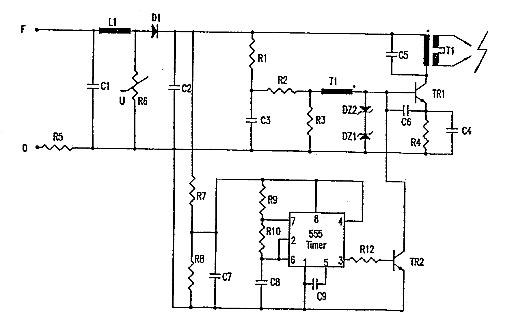
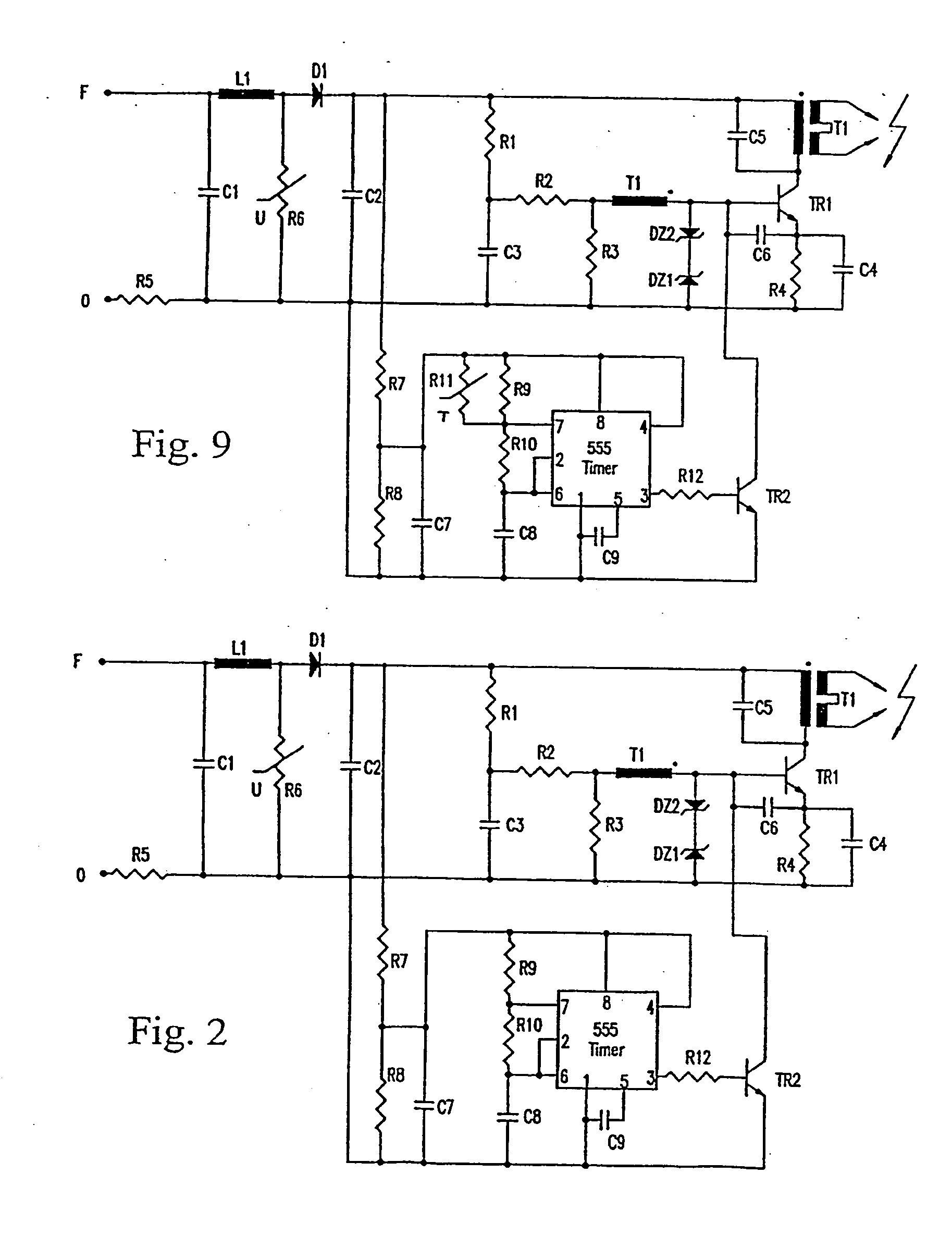
[0062] In a first embodiment, illustrated in FIG. 2, this is achieved by incorporating an on / off timer operating at a given duty cycle in the oscillator circuit.

[0063] The on / off timer is an astable timing circuit based on an integrated circuit commonly known as a 555 timer allowing a square signal with a given period to be output to the base of the transistor TR2. When the square signal is high the transistor TR2 conducts, thereby short circuiting the base of the transistor T1 to zero. Consequently the transistor TR1 is rendered non-conducting and thereby disables the oscillator circuit.

[0064] The on / off timer is supplied via a voltage divider R7, R8 with a smoothing capacitor C7 ensuring the supply of the timer between the voltage pulses from D1.

[0065] The 555 timer has two comparator inputs 6 and 7. During the time when the 555 timer is on the capacitor C8 is charged through the resistors R9 and R10. When the voltage difference between the inputs 6 and 7 falls below a predeterm...

second embodiment

[0081] According to the invention, illustrated in FIG. 3, the above resulting burst sequences may also be realised by means of electronic ignition circuitry comprising a combination of an on / off timer and the prior art circuit of FIG. 1. The timer is arranged so as to enable or disable the supply to the prior art ignition circuit. By interrupting the supply appropriately, some of the current supply pulses to the oscillator will be omitted and corresponding burst consequently not produced.

[0082] The timer could be replaced by a control box including a control circuit, which controls the overall operation of the burner system, where the control circuit enables and disables the supply to the prior art ignition circuit.

[0083] This has the advantage over the unit described above, that the prior art unit may still be used, and only supplemented with the timing circuit. The timing circuit may then have the same fixed values as described above, or it may be externally controllable to be sw...


PUM


Abstract

A method for ignition of an oil burner and electronic ignition circuitry for oil burners. Electronic ignition circuit for oil burners, for generating temporally spaced sparks. The electronic circuitry comprises circuitry for producing temporally spaced sparks with a spacing not corresponding to a half-period of the AC mains frequency or of a multiple of the AC mains frequency. The circuitry may be used in a method for ignition of an oil burner forming part of an oil burner system, where said oil burner comprises electronic circuitry for producing a first sequence of temporally spaced sparks for ignition of the oil. According to the method, the electronic circuitry is adjusted to subsequently produce a second sequence of temporally spaced sparks if it is detected that the ignition results in acoustic resonance in the oil burner system using said first sequence of temporally spaced sparks.

Description

CROSS-REFERENCE TO RELATED APPLICATIONS [0001] This application is entitled to the benefit of and incorporates by reference essential subject matter disclosed in International Patent Application No. PCT / DK02 / 00269 filed on Apr. 25, 2002.FIELD OF THE INVENTION [0002] The present invention relates to a method for ignition of an oil burner forming part of an oil burner system, where said oil burner comprises electronic circuitry for producing a first sequence of temporally spaced sparks for ignition of the oil, as well as to electronic ignition circuitry for oil burners, for generating temporally spaced sparks. BACKGROUND OF THE INVENTION [0003] In the oil burners typically for heating in single-family houses, electric ignition is employed. [0004] In such burners a blower creates an airflow into which the oil is sprayed through a spray nozzle to form an oil mist in the airflow. In order to ignite the oil an ignition spark gap is located in the vicinity of, but not too close to the spra...

Claims


Application Information

Patent Timeline
IPC IPC(8): F23Q3/00
CPCF23Q3/004F23Q3/00
Inventor ANDREASEN, LARS
Owner DANFOSS AS
Learn More