Transparent filtered capillaries

a transparent filter and capillary technology, applied in the field of capillary tubes, can solve the problems of particle loss, multiple wash cycles and incubations, and the need for additional handling and transferring of the particle mixture, and achieve the effect of reducing the labor intensity of the multiple wash cycles and incubations, and improving the efficiency of the assay

Inactive Publication Date: 2005-09-29
CORNING INC
View PDF27 Cites 28 Cited by
  • Summary
  • Abstract
  • Description
  • Claims
  • Application Information

AI Technical Summary

Benefits of technology

[0009] One aspect of the invention is a microfluidic reactor for trapping one or more particles of predetermined nominal size or range of sizes that have entered a flow inlet which includes a transparent reaction zone for also serves as an in-situ detection zone wherein the detection zone is arranged so as su...

Problems solved by technology

In both approaches, the multiple wash cycles and incubations are labor intensive and particle loss is a concerned when performing particle-based assays.
Clearly, both techniques require additional handling and transferring of the particle mixture.
It may lead to particle loss and hence a large number of particles may be required.
In the drying technique, it is very difficult to prevent particles from stacking to form a monolayer which will affect data analysis.
Also, complicated fluid handling is required in such conventional techniques which do not provide an efficient method of preparing the ...

Method used


Image

  • Transparent filtered capillaries
  • Transparent filtered capillaries
  • Transparent filtered capillaries

Examples


Embodiment Construction

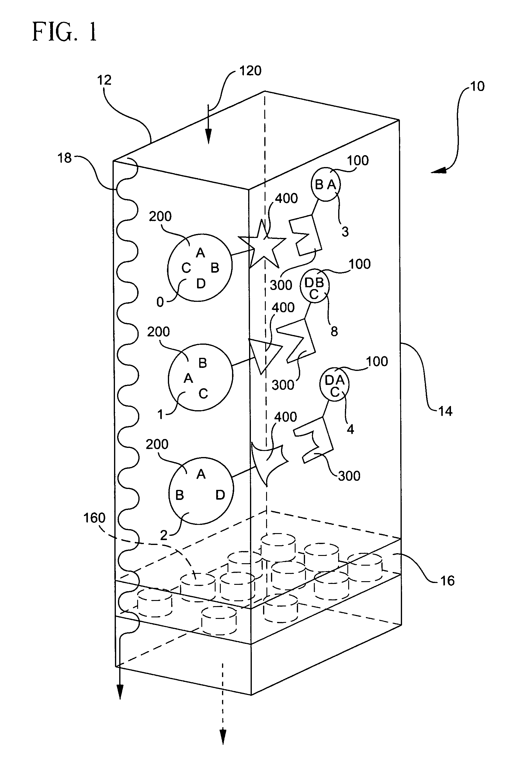
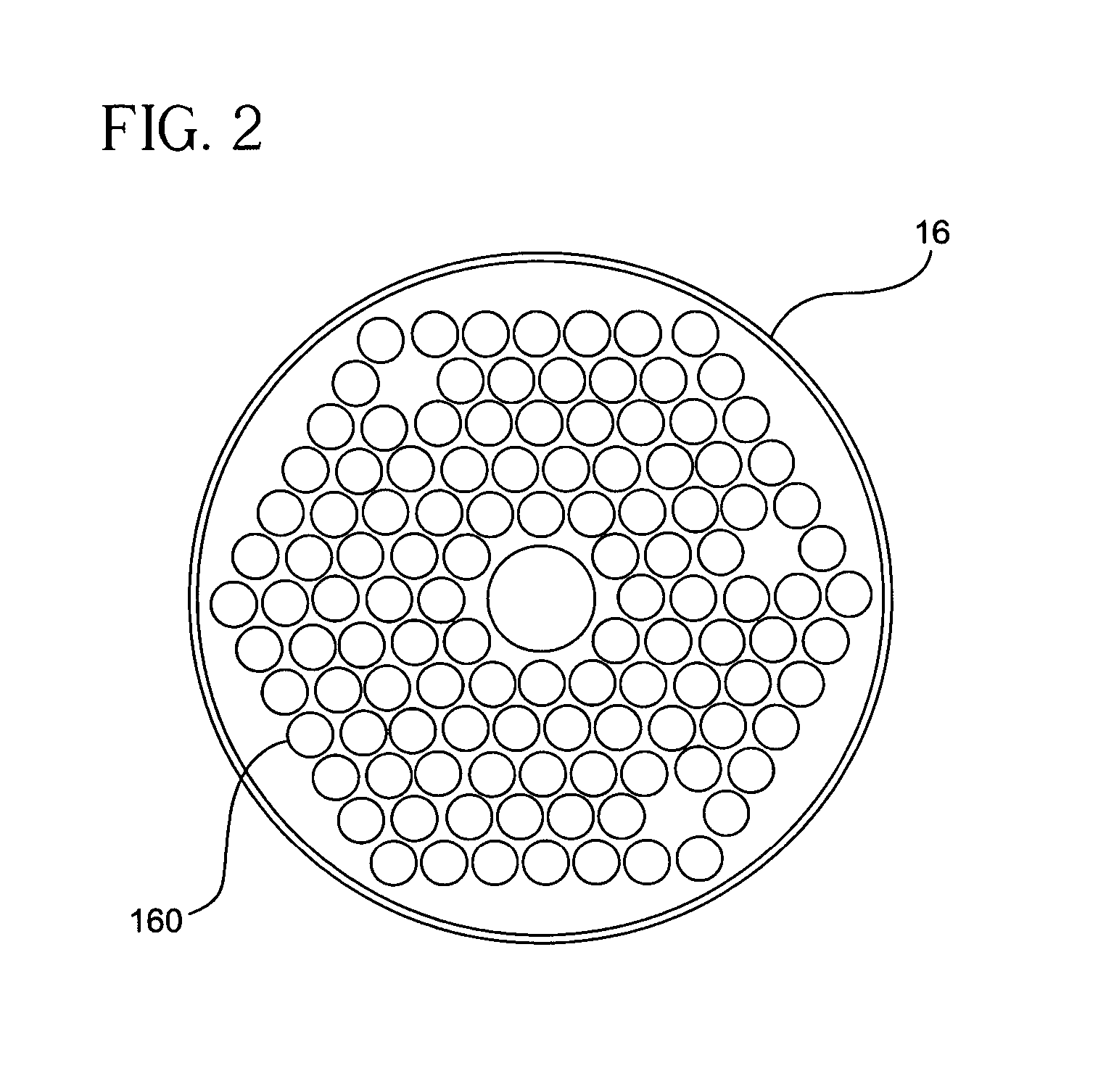
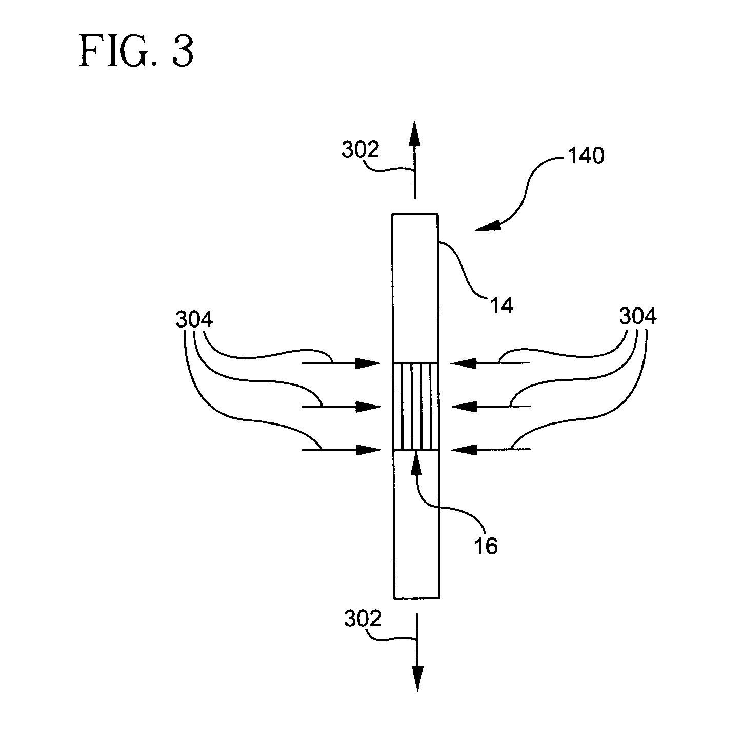
[0022] Reference will now be made in detail to the present preferred embodiments of the invention, examples of which are illustrated in the accompanying drawings. Whenever possible, the same reference numerals will be used throughout the drawings to refer to the same or like parts. One embodiment of the microfluidic reactor of the present invention is shown in FIG. 1, and is designated generally throughout by the reference numeral 10. In accordance with the invention, the present invention for a method and apparatus of microfluidic reaction includes a first element or step of trapping one or more particles of predetermined nominal size or range of sizes that have entered a flow inlet 12. A transparent reaction zone 14 serves as an in-situ detection zone wherein the detection zone is arranged so as substantially to correspond in shape to an optical detector 456, as represented in FIGS. 4, 5, and 6. A porous filter 16 having a plurality of holes 160 being smaller than the nominal size...


PUM


Abstract

A microfluidic reactor (10) for trapping one or more particles of predetermined nominal size or range of sizes that have entered a flow inlet (12) includes a transparent reaction zone (14) which also serves as an in-situ detection zone wherein the detection zone is arranged so as substantially to correspond in shape to an optical detector (456). A porous filter (16) having a plurality of holes (160) being smaller than the nominal size or range of sizes of the particles (200) are arranged so as to trap the particles in the reaction zone (14) while a fluid (18) flows from the flow inlet (12) through the reaction zone (14) and the filter (16).

Description

BACKGROUND OF THE INVENTION [0001] 1. Field of the Invention [0002] The present invention relates generally to high throughput biological assay devices, and particularly to capillary tubes in high throughput biological particle-based assay devices. [0003] 2. Technical Background [0004] Particle-based assays are known. With particle-based assays, biomolecular reactions take place either on the surface of microscopic beads called microspheres or microscopic bars called microrods (typical sizes are in the submicron and micron ranges). In order to use the particle-based assays to study the biomolecular reactions, for each reaction, a number of molecules are first immobilized or attached to the surface of the particles. These attached molecules are typically called probes. A sample solution containing target molecule(s) is applied to each well or tube and mixed with the “treated” particles. A target or analyte presented in the sample reacts with the probe molecules. In general, the targe...

Claims


Application Information

Patent Timeline
IPC IPC(8): B01L3/00G01N15/06G01N15/14
CPCB01J2219/00286B01J2219/00423B01J2219/00495B01J2219/005B01J2219/00722B01L3/502761G01N15/1484B01L2300/0681B01L2300/0809B01L2300/16G01N15/0625G01N15/1463B01L2200/0668C12M1/34C12Q1/00G01N15/14
Inventor DEJNEKA, MATTHEW J.RASMUSSEN, MICHAEL H.YUEN, PO KI
Owner CORNING INC
Why Eureka
Try Eureka