Apparatus and method for dynamic control of downlink beam width of an adaptive antenna array in a wireless network

a wireless network and adaptive antenna technology, applied in power management, transmission monitoring, receiver monitoring, etc., can solve the problems of not correcting the phase mismatch, introducing a new problem in the communication downlink, and reducing the beam width, so as to reduce the beam width, increase the beam width, and increase the beam width

Inactive Publication Date: 2005-09-29
SAMSUNG ELECTRONICS CO LTD
View PDF12 Cites 26 Cited by
  • Summary
  • Abstract
  • Description
  • Claims
  • Application Information

AI Technical Summary

Benefits of technology

[0010] According to one embodiment of the present invention, the base station further comprises an adaptive antenna array capable of facilitating the forming of the downlink beam by the beam forming circuitry.
[0014] According to a further embodiment of the present invention, the base station is further capable of decreasing the beam width of the traffic beam when the differential power control is equal to 0 or −1, increasing the beam width of said traffic beam when the differential power control is equal to +1 and the differential pilot strength is equal to +1 and decreasing the beam width of said traffic beam when the differential power control is equal to +1 and the differential pilot strength is equal to 0 or −1.

Problems solved by technology

However, the use of narrow beams introduces a new problem in the communication downlink.
Since the downlink channel associated with the pilot signal (e.g., wide beam) is different from the downlink channel associated with the traffic signal (e.g., narrow beam), the phase information extracted from the pilot signal may not accurately correlate with the traffic signal.
However, pre-calculating the beam forming coefficients for each segment is an inflexible solution that does not correct the phase mismatch equally across all areas of each segment.
In addition, a pre-calculated look-up table assumes a static physical environment, which is unrealistic in many urban areas.
Furthermore, the learning or calibration phase is a time consuming and computation intensive process.
Likewise, using the FER to calculate the beam width also involves lengthy computations, which can lead to a suboptimal choice of beam width.

Method used


Image

  • Apparatus and method for dynamic control of downlink beam width of an adaptive antenna array in a wireless network
  • Apparatus and method for dynamic control of downlink beam width of an adaptive antenna array in a wireless network
  • Apparatus and method for dynamic control of downlink beam width of an adaptive antenna array in a wireless network

Examples


Embodiment Construction

[0021]FIGS. 1 through 4, discussed below, and the various embodiments used to describe the principles of the present invention in this patent document are by way of illustration only and should not be construed in any way to limit the scope of the invention. Those skilled in the art will understand that the principles of the present invention may be implemented in any suitably arranged wireless network.

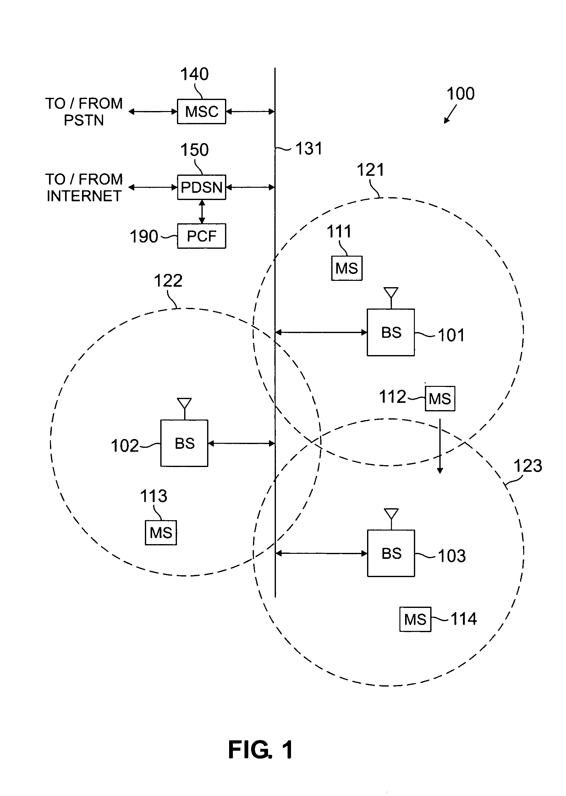
[0022]FIG. 1 illustrates exemplary wireless network 100, in which beam widths are optimized according to the principles of the present invention. Wireless network 100 comprises a plurality of cell sites 121-123, each containing one of the base stations, BS 101, BS 102, or BS 103. Base stations 101-103 communicate with a plurality of mobile stations (MS) 111-114 over code division multiple access (CDMA) channels according to, for example, the IS-2000-C standard (i.e., Release C of cdma2000). In an advantageous embodiment of the present invention, mobile stations 111-114 are capable of...


PUM


Abstract

A wireless network base station for optimizing the beam width of a downlink traffic beam in real time is provided. The base station includes a transceiver for receiving a pilot strength signal and a power control signal from a mobile station. The base station further includes beam forming circuitry operable to form a downlink traffic beam spatially directed to serve the mobile station having a beam width set as a function of the received pilot strength signal and power control signal.

Description

TECHNICAL FIELD OF THE INVENTION [0001] The present invention is directed generally to wireless networks and, more specifically, to a technique for dynamically adjusting an adaptive antenna array to select an optimum beam width for transmitting in a wireless network. BACKGROUND OF THE INVENTION [0002] Wireless communication systems have become ubiquitous in society. Business and consumers use a wide variety of fixed and mobile wireless terminals, including cell phones, pagers, Personal Communication Services (PCS) systems, and fixed wireless access devices (i.e., vending machine with cellular capability). Wireless service providers continually try to create new markets for wireless devices and expand existing markets by making wireless devices and services cheaper and more reliable. [0003] In code division multiple access (CDMA) networks, for example, adaptive antenna arrays have been developed to increase the capacity and quality of calls handled within CDMA networks. Adaptive ante...

Claims


Application Information

Patent Timeline
Patent Type & Authority Applications(United States)
IPC IPC(8): H04B1/38H04B7/005H04B7/26H04B17/00H04M1/00H04W52/08H04W52/22H04W52/24
CPCH04W52/08H04W52/221H04B17/318H04B17/24H04W52/245A21C11/18
Inventor RENSBURG, CORNELIUS VANRAJKOTIA, PURVA R.
Owner SAMSUNG ELECTRONICS CO LTD
Why Eureka
Try Eureka