Cardiac drug delivery system and method of use

Inactive Publication Date: 2005-09-29
BIOCARDIA
View PDF15 Cites 137 Cited by
  • Summary
  • Abstract
  • Description
  • Claims
  • Application Information

AI Technical Summary

Benefits of technology

[0016] In general it is an object of the present invention to provide a biocompatible drug delivery catheter which will improve the ability to deliver drugs to a depth within the heart tissue.
[0017] Another object of the invention is the delivery of growth factors to a depth within the heart tissue over an extended period of time to increase collateral flow in poorly perfPat.uised tissue.
[0018] Yet another object of the invention is to provide a permanently implantable system that will enable transient delivery of pharmacological agents to a depth within the heart tissue such that cardiac arrhythmias may be terminated.
[

Problems solved by technology

Ischemic tissue is characterized by limited metabolic processes which cause poor functionality.
The tissue lacks oxygen, nutrients, and means for disposing of wastes.
This hinders the normal functioning of the heart cells or myocytes in an ischemic region.
It should be noted that these therapies are primarily for the treatment of large vessel disease, and that many patients suffer from poor perfusion within smaller vessels that cannot be treated with conventional therapies.
Recently similar techniques have been attempted in peripheral vessels in human patients with the primary difficulty being systemic effects of the agents delivered.
U.S. Pat. No. 5,244,460 issued to Unger describes a method of introducing growth factors over time by delivering them through fluid catheters into the coronary arteries, but this does not result in efficient delivery of these agents to the ischemic tissue.
Further, growth factors may cause unwanted angiogenesis in tissues where inappropriately delivered.
Further, placement of delivery devices within these coronary arteries as Unger describes tends to obstruct these arteries and may augment occlusive thrombosis formation.
Aft

Method used


Image

  • Cardiac drug delivery system and method of use
  • Cardiac drug delivery system and method of use
  • Cardiac drug delivery system and method of use

Examples


Embodiment Construction

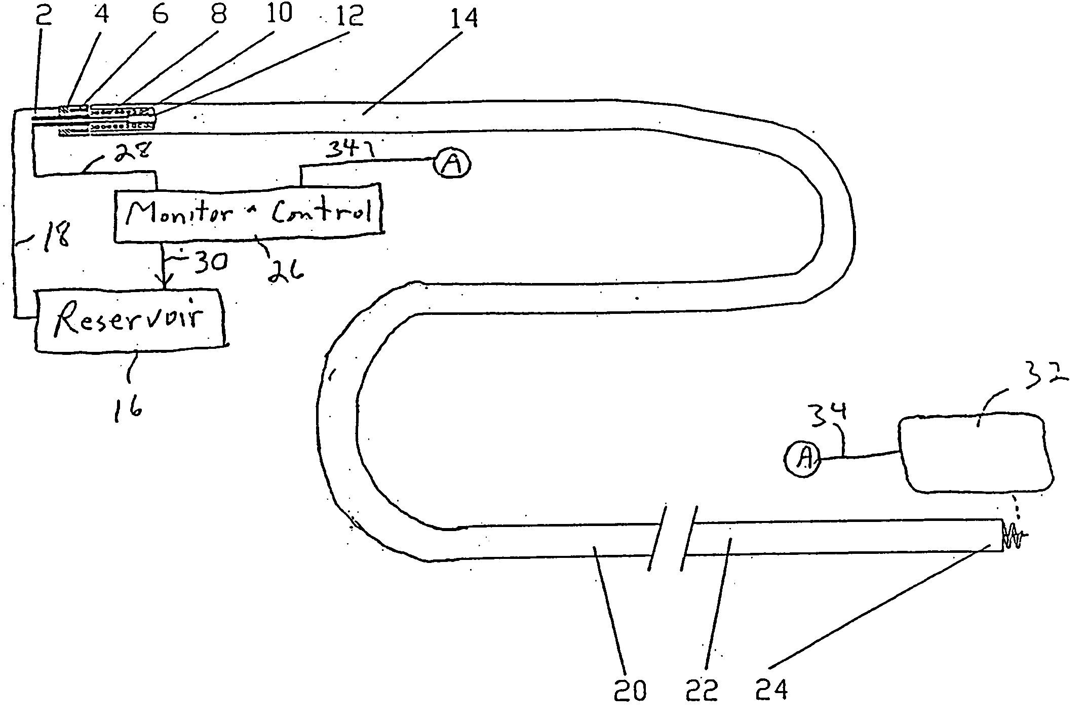
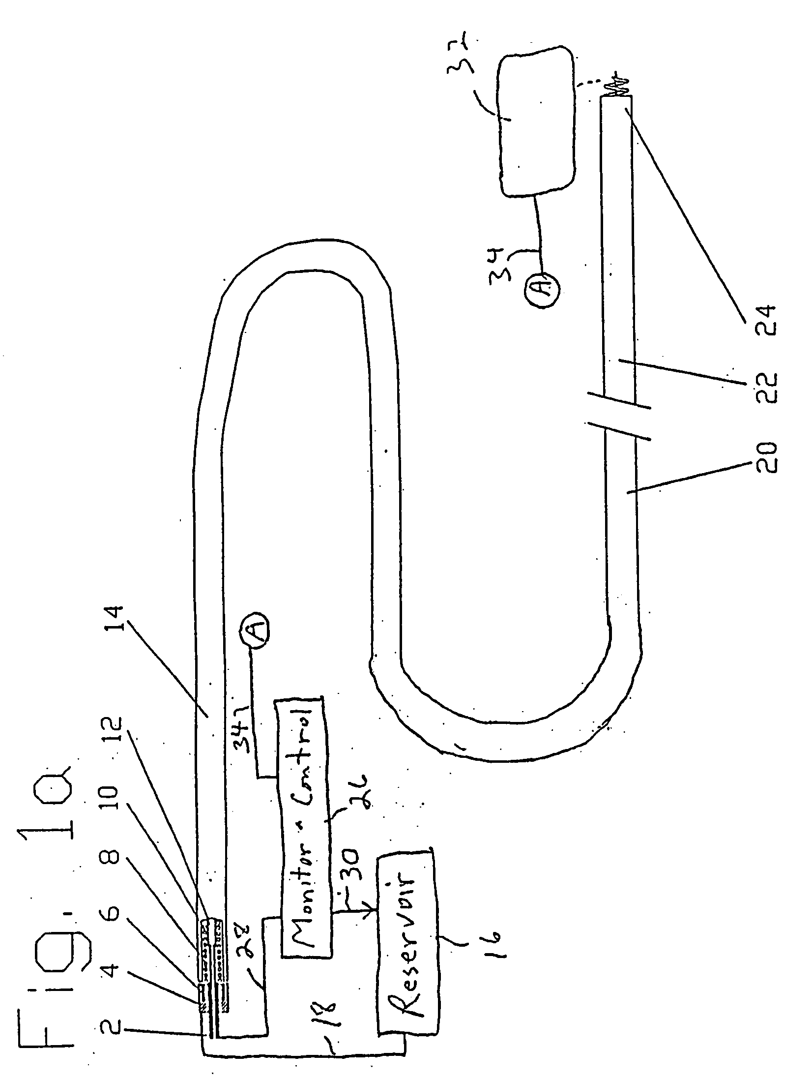
[0043] New concepts for delivering agents for the treatment of heart failure, ischemia, arrhythmias, and restenosis are disclosed. The main embodiments consist of transvenous or transarterial catheter delivery techniques for delivering agents directly to a chosen site within the heart at a depth within the heart tissue. Hollow helical delivery devices, needle delivery devices, and implantable controlled release matrices may be inserted such that metabolic agents, anti ischemic agents, growth factors, antiarrhythmic agents, anti-inflammatory agents anti-proliferative agents, gene therapy preparations, and combinations of these agents may be delivered directly to the tissue that can benefit most from these agents.

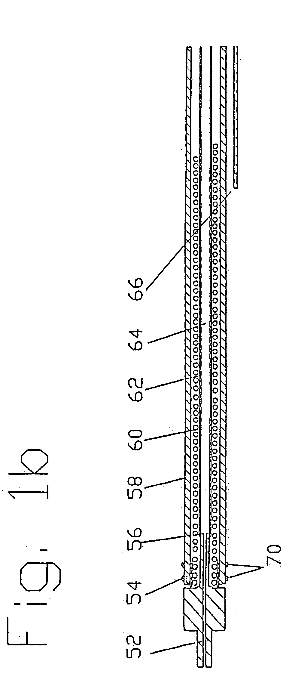
[0044] These drug delivery structures may be made from different materials depending upon whether the device is to be used chronically or acutely. For example, metal components in the preferred implantable embodiments, formed of a Platinum Iridium alloy consisting of ninety ...


PUM

PropertyMeasurementUnit
Volumeaaaaaaaaaa
Flexibilityaaaaaaaaaa
Depthaaaaaaaaaa

Abstract

A system is disclosed, for administering a therapeutic agent locally and to a depth within cardiac tissue. An elongate, flexible catheter contains a flexible electric conductor and supports at its distal end an implantable electrode incorporating a penetrating element, typically a fixation helix or a linear needle that penetrates cardiac tissue as the electrode is implanted. A therapeutic agent is delivered through the electrode, to the cardiac tissue surrounding the penetrating element. The electrode can act as a sensor to monitor an electrical condition of the surrounding cardiac tissue and to control delivery of the agent responsive to the sensed electrical condition. Several embodiments feature a distal reservoir adjacent the electrode, for effecting transient deliveries of the therapeutic agent in minute quantities. Other embodiments are disclosed for providing sustained deliveries of agents.

Description

[0001] This is a divisional of copending prior application Ser. No. 10 / 101,301, filed Mar. 19, 2002 as a divisional of application Ser. No. 09 / 260,641 (now U.S. Pat. No. 6,358,247), filed Mar. 2, 1999 as a divisional of application Ser. No. 08 / 816,850 (now U.S. Pat. No. 6,086,582), filed Mar. 13, 1997.FIELD OF THE INVENTION [0002] This invention relates to site specific delivery of therapeutic agents, structures and catheter systems to achieve site specific delivery of therapeutic agents, and means for implanting and using these systems to enable delivery of therapeutic agents to the body. More specifically, this invention relates to delivery of pharmacological agents to specific regions of the heart at a depth within the heart wall. BACKGROUND OF THE INVENTION [0003] It is possible to identify particular sites within the myocardium which may benefit from local drug release therapy. Examples of problematic tissue which may benefit form local drug release therapy are ischemic sites a...

Claims


Application Information

Patent Timeline
IPC IPC(8): A61B17/00A61B18/14A61B18/18A61K9/127A61K9/16A61K9/50A61M5/178A61M25/00A61N1/05
CPCA61B18/1492B82Y5/00A61B2018/00011A61B2018/00273A61B2018/00351A61B2018/00392A61B2018/00577A61B2018/00839A61B2018/1425A61B2018/1435A61B2218/002A61K9/127A61K9/1676A61K9/50A61M25/0084A61M2025/0089A61N1/0575A61B2017/00247
Inventor ALTMAN, PETER A.ALTMAN, JOHN D.
Owner BIOCARDIA
Why Eureka
Try Eureka