Exhaust emission control system for internal combustion engine

a technology of emission control system and internal combustion engine, which is applied in the direction of electrical control, exhaust treatment electric control, separation process, etc., can solve the problems of increasing engine backpressure, reducing engine power, and difficult to accurately estimate the amount of particulate matter in the particulate filter, so as to increase the detection accuracy of differential pressure and avoid over-cash. , the effect of increasing the cos

Active Publication Date: 2005-10-06
DENSO CORP
View PDF7 Cites 24 Cited by
  • Summary
  • Abstract
  • Description
  • Claims
  • Application Information

AI Technical Summary

Benefits of technology

[0009] The object of the present invention, in view of the above issues, is to provide an exhaust emission control system for an internal combustion engine that can clean a particulate filter provided with the engine according to a proper schedule without an excessive cost increase.
[0010] To achieve the above object, an exhaust emission control system according to the present invention is for an internal combustion engine and located on a vehicle and provided with a particulate filter to accumulate particulate matters in an exhaust gas of the engine. The system has a pressure difference detector, an exhaust flow rate detector, a regeneration controller, and a detection accuracy increaser. The pressure difference detector detects a differential pressure in the particulate filter. The exhaust flow rate detector detects an exhaust flow rate of the engine. The regeneration controller determines to regenerate the particulate filter based on the differential pressure and the exhaust flow rate. The detection accuracy increaser increases a detection accuracy of the differential pressure.

Problems solved by technology

Further, it is a current issue to eliminate particulate matters such as soot and soluble organic fraction (SOF) in the exhaust gas of a diesel engine.
A large amount of the particulate matters in the particulate filter increases a flow resistance of the exhaust gas and a backpressure of the engine and decreases a power of the engine.
However, both the exhaust flow rate and the differential pressure fluctuate making it difficult to accurately estimate the amount of the particulate matters in the particulate filter.
Providing a low estimate of the amount of particulate may cause an increase in backpressure of the engine and a decrease in engine power, as described above.
Furthermore, the rapid burning of the large amount of the particulate matters deteriorates the particulate filter fast.
Providing a high estimate of the amount increases the time of burning the particulate matters and wears the particulate filter fast, thereby causing it to be replaced.
A sensor system for estimating the particulate amount with high accuracy increases a manufacturing cost.

Method used


Image

  • Exhaust emission control system for internal combustion engine
  • Exhaust emission control system for internal combustion engine
  • Exhaust emission control system for internal combustion engine

Examples


first embodiment

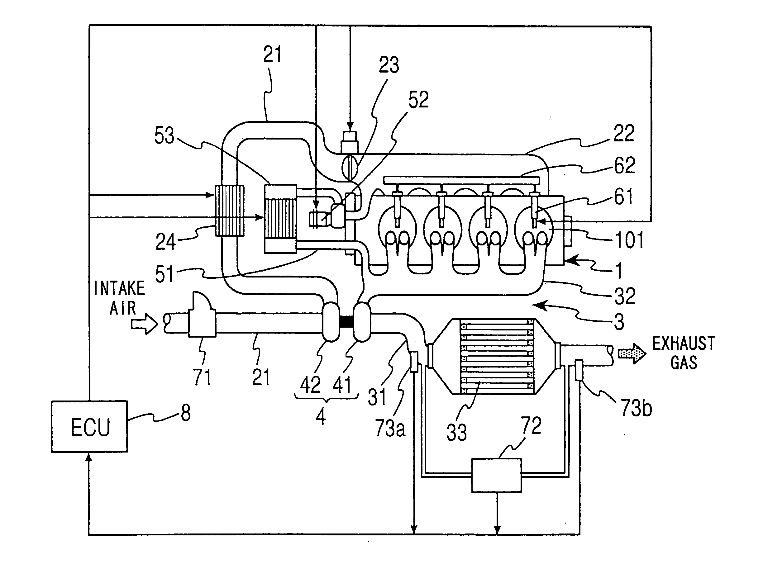
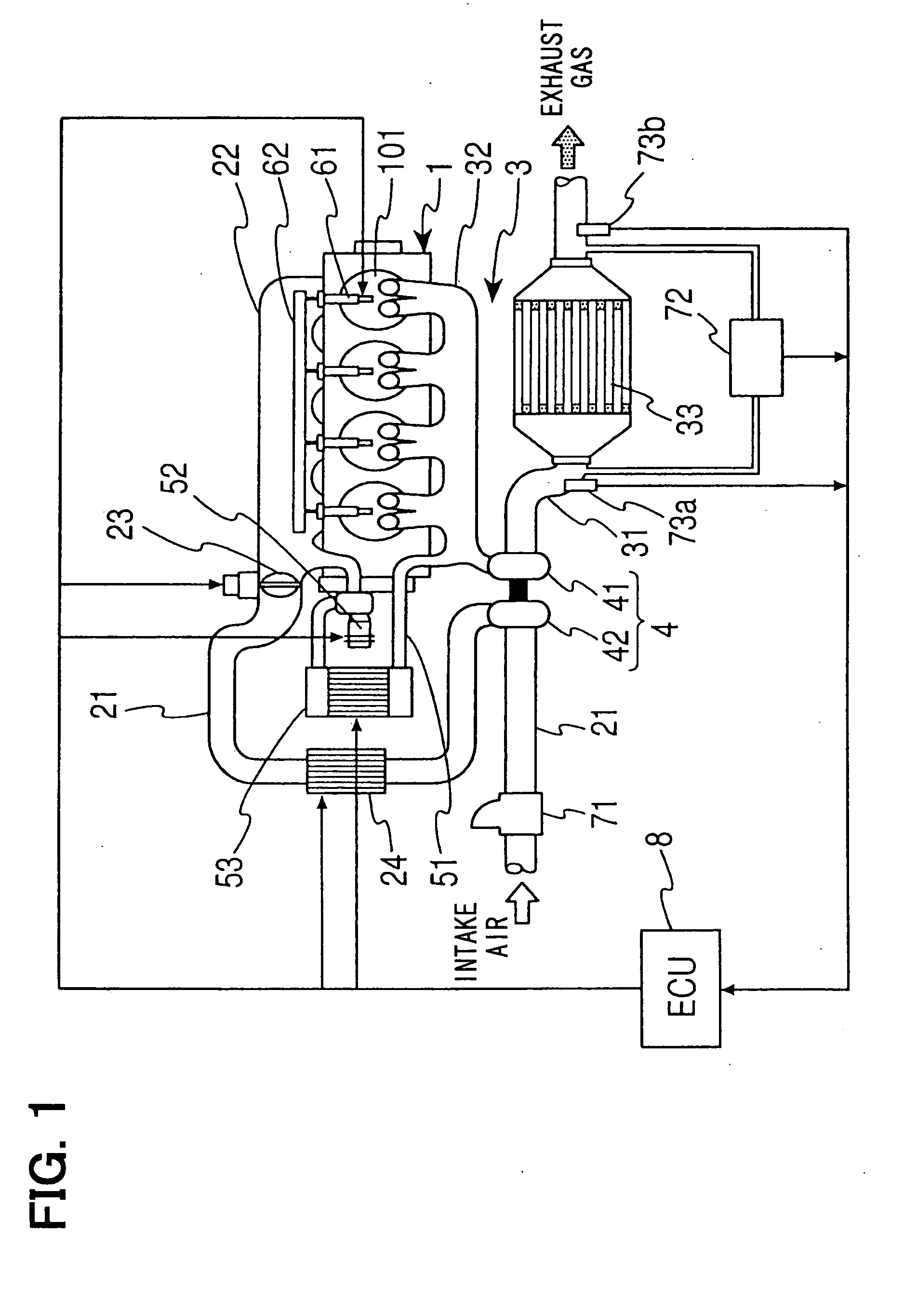
[0026] the present invention, as shown in FIG. 1, has an exhaust emission control system for removing particulate matters in an exhaust gas of a diesel engine (an internal combustion engine) 1. The engine 1 has a plurality of fuel injectors 61 and a common rail 62 in communication with each of the fuel injectors 61. The fuel injectors 61 inject a fuel supplied from the common rail 62 into combustion chambers of cylinders of the engine 1.

[0027] An intake pipe 21 and an intake manifold 22 of the engine 1 are connected to each other. An intake throttle valve 23 is interposed between the intake pipe 21 and the intake manifold 22 for adjusting an intake flow rate. The intake pipe 21 has an airflow meter 71 for detecting the intake flow rate.

[0028] An exhaust gas of the engine 1 flows out of exhaust ports 101 of the engine 1 and through an exhaust passage 3. The exhaust passage 3 includes an exhaust pipe 31 and an exhaust manifold 32 connected to each other. The exhaust pipe 31 is provid...

second embodiment

[0052] the present invention removes particulate matters in the DPF 33 by a control process shown in FIG. 7.

[0053] In steps S201 to S207, the ECU 8 identifies a maximum exhaust flow rate during a predetermined time. In step S201, the ECU 8 sets a variable k to zero. In step S202, the ECU 8 increments the variable k by one.

[0054] In steps S203, the ECU 8 detects the intake flow rate, the exhaust temperature, and the differential pressure. In step S204, the ECU 8 calculates the exhaust flow rate with the intake flow rate, the exhaust temperature, and the differential pressure. The steps S203 and S204 are substantially the same as the steps S101 and S102 in the first embodiment.

[0055] In step S205, the ECU 8 stores the exhaust flow rate in a RAM provided in the ECU 8. The RAM is configured to be able to store n pairs of the exhaust flow rates and the differential pressures as described below, wherein n denotes a constant number.

[0056] In step S206, the ECU 8 determines whether the v...

third embodiment

[0071] Thus, the exhaust emission control system of the third embodiment raises the accuracy of the analog output voltage of the pressure difference sensor 72 by (P0 / Pmax) times when the analog output voltage is not sufficiently large for estimating the particulate accumulation amount. Accordingly, the system can estimate the particulate accumulation amount with high accuracy even when the exhaust flow rate is not sufficiently large for the estimation.

[0072] Alternatively, the process of the step S303 may be done as a comparison of the exhaust flow rate and a threshold value.

[0073]FIG. 11 depicts a fourth embodiment of the present invention having an ECU 8B that has a different configuration from the ECU 8A in the third embodiment for removing particulate matters in the DPF 33. FIG. 11 schematically depicts a signal processing unit 80B in the ECU 8B.

[0074] The signal processing unit 80B can change an input-to-output ratio of the signal. Specifically, the signal processing unit 80B...


PUM

PropertyMeasurementUnit
pressure difference detectoraaaaaaaaaa
pressureaaaaaaaaaa
exhaust flow rateaaaaaaaaaa

Abstract

An exhaust emission control system for an internal combustion engine is located on a vehicle and provided with a particulate filter to accumulate particulate matters in an exhaust gas of the engine. The system has a pressure difference detector, an exhaust flow rate detector, a regeneration controller and a detection accuracy increaser. The pressure difference detector detects a differential pressure in the particulate filter. The exhaust flow rate detector detects an exhaust flow rate of the engine. The regeneration controller determines to regenerate the particulate filter based on the differential pressure and the exhaust flow rate. The detection accuracy increaser increases a detection accuracy of the differential pressure.

Description

CROSS REFERENCE TO RELATED APPLICATION [0001] This application is based upon and claims the benefit of priority of Japanese Patent Application No. 2004-110750 filed on Apr. 5, 2004, the content of which is incorporated herein by reference. FIELD OF THE INVENTION [0002] The present invention relates to an exhaust emission control system for an internal combustion engine provided with a particulate filter for removing particulate matters in an exhaust gas and, more particularly, a system optimized for determining a proper schedule to regenerate the particulate filter. BACKGROUND OF THE INVENTION [0003] Conventionally, an internal combustion engine adopts an exhaust emission control system such as an oxidation catalyst, nitrogen oxide catalyst, or a three way catalyst, for removing airborne pollutants in an exhaust gas of the engine as a measure for environmental protection. Further, it is a current issue to eliminate particulate matters such as soot and soluble organic fraction (SOF) ...

Claims


Application Information

Patent Timeline
Patent Type & Authority Applications(United States)
IPC IPC(8): B60W10/04B01D46/42B01D53/94B60W10/06B60W10/10B60W10/11F01N3/00F01N3/02F01N3/023F01N3/025F01N3/029F01N9/00F02B29/04F02B37/00F02B37/22F02B37/24F02D9/02F02D21/08F02D23/00F02D29/00F02D41/02F02D41/14F02D41/38F02D43/00F02D45/00F02M25/07
CPCF01N3/023Y02T10/47F01N9/002F01N9/005F01N2330/06F01N2430/06F01N2430/08F01N2430/085F01N2510/065F02B29/0406F02B37/00F02B37/24F02D41/029F02D41/1445F02D41/1448F02D41/187F02M25/0707F02M25/0727F01N3/0253F02M26/05F02M26/23Y02T10/40
Inventor KUBOSHIMA, TSUKASAKINUGAWA, MASUMI
Owner DENSO CORP
Why Eureka
Try Eureka