Monitoring electrolytic cell currents

a technology of electrolytic cells and current monitoring, applied in the direction of voltage/current isolation, electrolysis components, instruments, etc., can solve the problems of short circuits, reduced efficiency of electrical use, and disruption of copper plating process, so as to improve electrode quality and increase energy utilization and efficiency

Inactive Publication Date: 2005-10-06
KENNECOTT UTAH COPPER
View PDF42 Cites 27 Cited by
  • Summary
  • Abstract
  • Description
  • Claims
  • Application Information

AI Technical Summary

Problems solved by technology

As subsequently elaborated upon, short circuits can occur if the anodes and cathodes are mis-aligned or if copper deposits on the cathode grow in a non uniform manner and contact the anode.
When short circuits do occur, the desired copper plating process is disrupted and the efficiency of electrical use decreases.
As subsequently elaborated upon, short circuits can occur if the anodes and cathodes are mis-aligned or if copper deposits on the cathode grow in a non-uniform manner and contact the anode.
When short circuits do occur, the desired copper plating process is disrupted.
Open circuits, on the other hand, can occur if there is poor contact between the current supply and the anodes or cathodes.
Failure to adequately monitor this cell parameter, and others, can reduce metal recovery, increase scrap rate, and lead to inefficient energy utilization.
Nevertheless, open and short circuits commonly occur during the electrolytic refining of copper.
They occur for many reasons, including i) poor anode and cathode physical qualities, ii) poor contact between the current supply and the anodes or cathodes, iii) misalignment of anodes and cathodes, and iv) localized variations in electrolyte temperature, additive levels, or chemistry.
Thus, efficient electrolytic cell monitoring is important during the electrolytic refining of copper, as it can enable system operators to detect open and short circuits between anodes and cathodes, which, if not corrected, reduce current efficiencies and result in down-stream processing problems, such as poor cathode development.
As known, copper impurity, copper content, and copper appearance are also ultimately adversely affected by open and short circuits.
Regardless, the task was both ergonomically difficult and accident-prone.
Moreover, walking on the cells frequently misaligned the anode and cathodes, could lead to possible contamination, and often lead to further problems as well.
However, like the traditional Gauss meter techniques, these generally only detect short circuits and not open circuits.
Unfortunately, however, many open and short circuits are not often detected until after significant damage has already occurred.

Method used


Image

  • Monitoring electrolytic cell currents
  • Monitoring electrolytic cell currents
  • Monitoring electrolytic cell currents

Examples


second embodiment

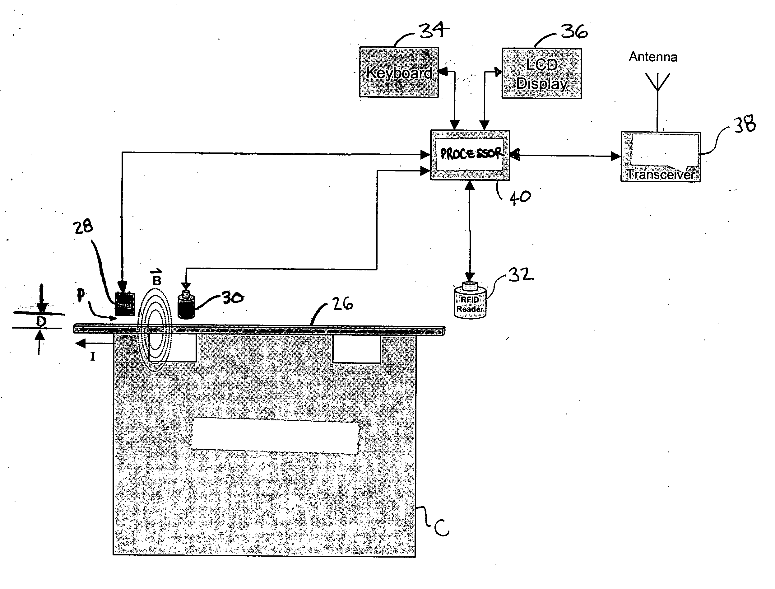
[0088] More specifically, FIGS. 12-13 depict a pole device 52 according to the invention, in which a Hall Effect sensor array 54 incorporates one or more Hall Effect sensors 28, preferably one Hall Effect sensor 28 for each cathode C of each electrolytic cell 22, thereby enabling simultaneous measurement of multiple cathodes C, including, for example, all of the cathodes C of the electrolytic cell 22.

[0089] In such an embodiment, the Hall Effect sensor array 54 may be connected to a processing head 56 for processing data therefrom, the processing head 56 containing one or more of the keyboard 34, LCD display 36 or the like, transceiver 38, or the processor 40 (not shown).

[0090] In addition, the Hall Effect sensor array 54 may also include one or more LEDs 58 associated with the Hall Effect sensor 28 for visually indicating the status of the electrolytic cell 22 being monitored. For example, a first (e.g. red) LED could indicate the presence of a short circuit while a second (e.g., ...

third embodiment

[0091] Likewise, FIG. 14 depicts a rail car device 58 according to the invention, in which the Hall Effect sensor array 54 incorporates one or more Hall Effect sensors 28, preferably one Hall Effect sensor 28 for each cathode C of each electrolytic cell 22, thereby enabling simultaneous measurement of multiple cathodes C, the Hall Effect sensor array 54 carried by the rail car device 58 along a pair of rails 60 or the like and connected to the processing head 56 for processing data therefrom.

fourth embodiment

[0092] According to the invention (not shown), an overhead crane, robotic, or other device can also carry out the inventive arrangements, in which the Hall Effect sensor array 54 incorporates one or more Hall Effect sensors 28, preferably one Hall Effect sensor 28 for each cathode C of each electrolytic cell 22, thereby enabling simultaneous measurement of multiple cathodes C, the Hall Effect sensor array 54 carried by the overhead crane, robotic, or other device and likely connected to a processing head 56 for processing data therefrom.

[0093] As described, those skilled in the art will recognize that many of the inventive arrangements can be realized in hardware, software, firmware, or any various combinations thereof. Moreover, any kind of processor 40, or other apparatus, adapted for carrying out the inventive arrangements described herein is suited. A typical combination of hardware and software, for example, could be a general purpose microprocessor chips (e.g., MPU) with a com...


PUM

PropertyMeasurementUnit
weight percentaaaaaaaaaa
distanceaaaaaaaaaa
distanceaaaaaaaaaa

Abstract

For an electrolytic cell, an apparatus and method are described that use one or more sensors to measure magnetic field strength about a conductor carrying electrical current. A processor is in electrical communication with the sensors and determines a compensated magnetic field strength based on the magnetic fields of other conductors that also carry electrical current to or from the electrolytic cell. The processor uses this compensated magnetic field strength to determine the cathode electrical current carried by the conductor and to identify open and short circuits between the anodes and cathodes of the cell. The described apparatus and method account for interactions between the magnetic fields of the neighboring cathodes.

Description

CROSS-REFERENCES TO RELATED APPLICATIONS [0001] This application claims priority under 35 U.S.C. §119(e) to Provisional Patent Application Ser. No. 60 / 553,899, filed on Mar. 17, 2004, the entire disclosure of which is hereby incorporated by reference.BACKGROUND OF THE INVENTION [0002] 1. Field of the Invention [0003] This invention relates to electrolytic cell monitoring for electrometallurgical systems, including, for example, i) electrorefining and electrowinning systems for copper, zinc, nickel, lead, cobalt, and other like metals, ii) electrochemical cells, such as chlor-alkali systems, and iii) molten salt electrolysis, such as aluminum and magnesium electrolysis. [0004] Insofar as the inventive arrangements can be used with electrolytic cell monitoring during a copper refinement stage of producing copper, copper production will be described hereinout for exemplary, representative, and non-limiting purposes. [0005] 2. Description of Related Art [0006] Producing copper involves ...

Claims


Application Information

Patent Timeline
Patent Type & Authority Applications(United States)
IPC IPC(8): C25B15/02C25B15/06C25C7/06C25D21/12G01R15/20
CPCC25B15/02C25B15/06G01R15/207C25D21/12C25C7/06Y02P10/20
Inventor YOU, EUGENE YANJUNBERGES-DREYFOUS, ANTONIOGEORGE, DAVID B.KIM, DANIELZHOU, KEMING
Owner KENNECOTT UTAH COPPER
Why Eureka
Try Eureka