
Two tier brazing for joining copper tubes to manifolds

a technology of copper alloy tubes and manifolds, which is applied in the direction of manufacturing tools, solvents, etc., can solve the problems of changing the microstructure of copper, the inability to terminate the braze cycle, and the alloying and erosion of the conventional method of furnace brazing copper tubes directly to metal manifolds in vacuum braze furnaces, etc., to achieve efficient joining and facilitate the joining of copper tubes

Inactive Publication Date: 2005-10-06
UNITED TECH CORP
View PDF17 Cites 11 Cited by
  • Summary
  • Abstract
  • Description
  • Claims
  • Application Information

AI Technical Summary

Benefits of technology

[0011] It is another object of the present invention to provide a two step brazing process which allows copper tubes to be efficiently joined to a metal manifold.
[0013] It is yet another object of the present invention to provide an improved method of brazing copper tube-ferrule assembly to a metal manifold.

Problems solved by technology

The conventional method of furnace brazing copper tubes directly to metal manifolds in a vacuum braze furnace has long presented problems with respect to alloying and erosion.
Since vacuum braze furnaces do not allow for any significant observation of the braze joint during heating and additionally must cool a significant mass of tooling and equipment from the brazing temperature, the braze cycle cannot be terminated the moment the braze melts and fills the joint.
These conditions very often lead to the interaction of copper alloy tubes with braze filler resulting in changes the microstructure of the copper, which generally reduces its strength, ductility and thermal conductivity.
By contrast, furnace brazing as stated above, requires the tubes to be directly brazed to the manifolds in a vacuum braze furnace which does not allow for visual monitoring of the braze joint during heating, the braze cycle (and thus continued heating) cannot therefore be terminated the moment the braze metals and fills the joint.
These conditions therefore usually result in a greater amount of superheat than that involved in focused heating source methods.

Method used


Image

  • Two tier brazing for joining copper tubes to manifolds
  • Two tier brazing for joining copper tubes to manifolds
  • Two tier brazing for joining copper tubes to manifolds

Examples


Embodiment Construction

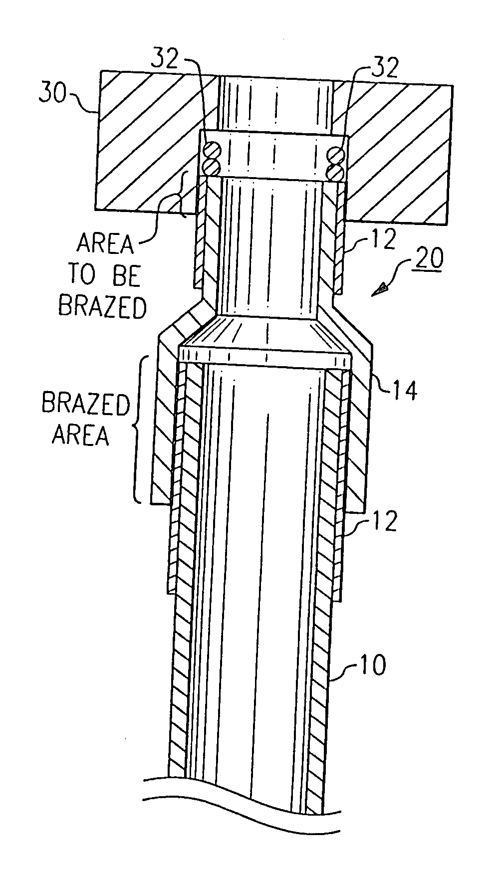
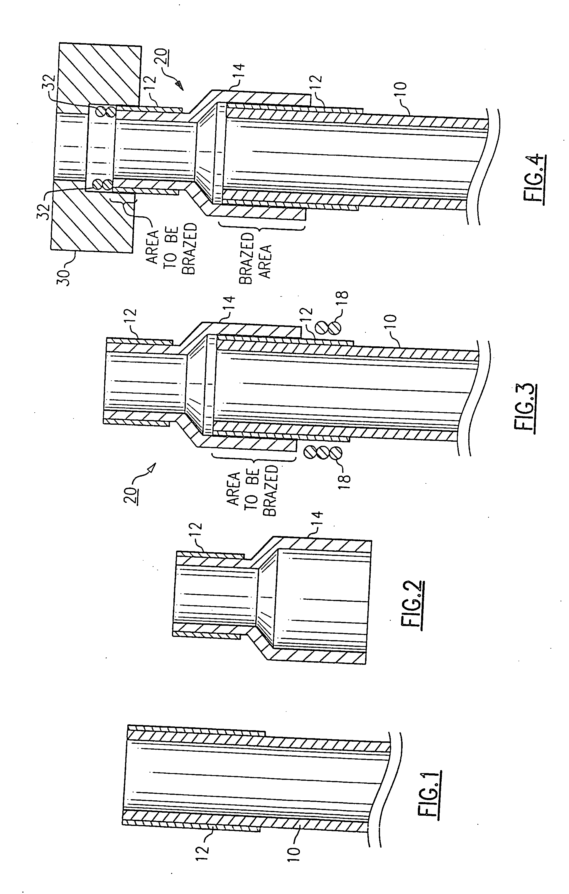
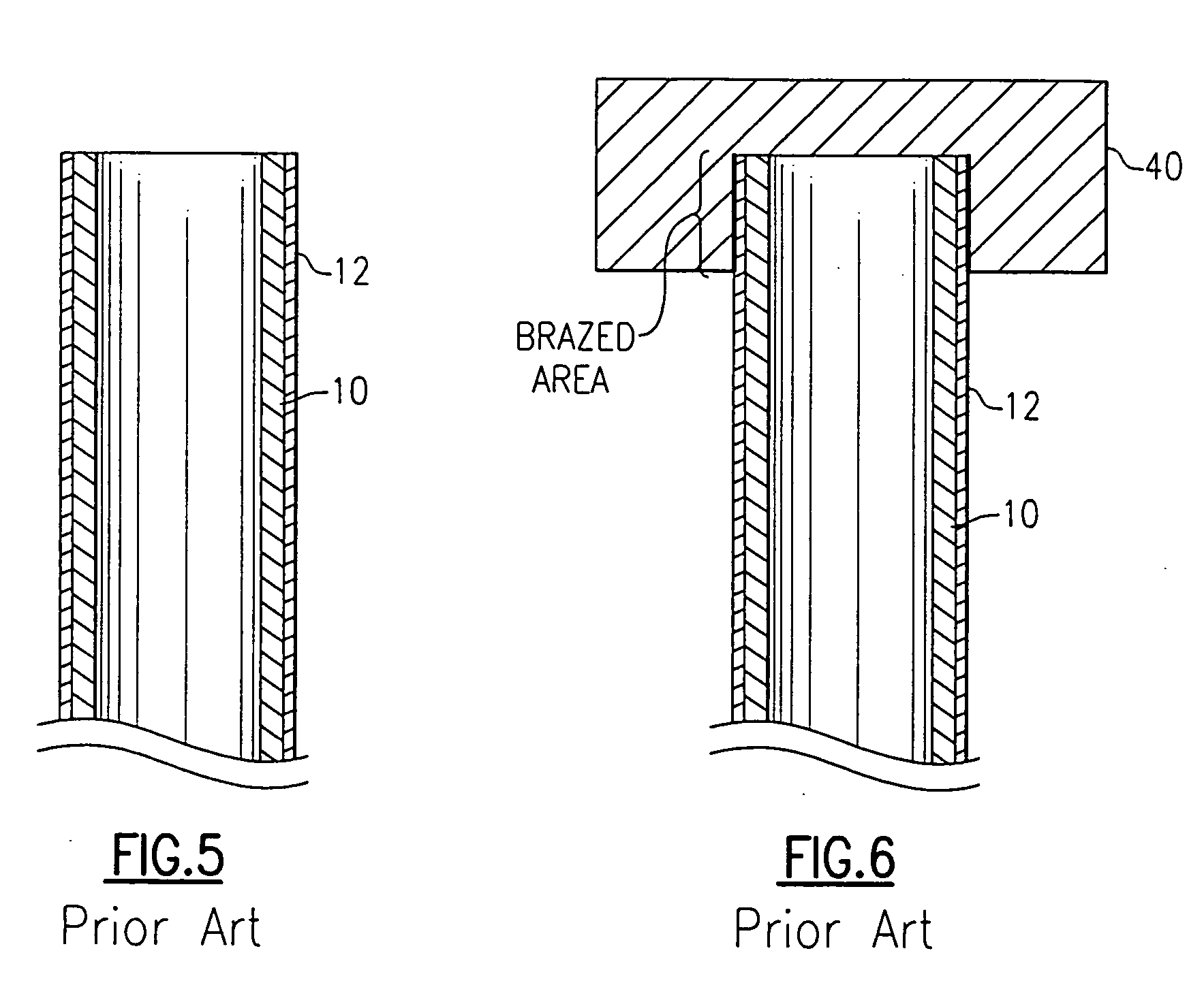
[0024] The process of the present invention provides significant improvement over the conventional technique described in FIGS. 5 and 6 of the drawings. Conventional methods involve providing a copper or copper alloy tube 10 and plating or coating the entire length of the tube with the noble metal 12. The coated or plated copper tube is then brazed directly to a manifold 40 as illustrated in FIG. 6. Typical problems associated with this technique occur where the plating over the entire surface of the copper tube is not uniform. When this occurs, a high risk of failure results due to imperfections in the plating or coating surface resulting in the brazing material alloying with the copper tube and deleteriously effecting the mechanical and physical properties of the copper tubes. Through the use of the present invention, the ferrule part of the copper tube-ferrule assembly can be brazed effectively to a compatible alloy or metal of the manifold, and therefore avoid the problems assoc...


PUM

PropertyMeasurementUnit
heataaaaaaaaaa
melting temperatureaaaaaaaaaa
temperatureaaaaaaaaaa

Abstract

A brazing process for joining copper and copper alloy tubes to a fitting which includes first forming a layer of a high melting temperature noble metal on one end of a copper or copper alloy tube. The plated end is then brazed to a metal ferrule to form a copper alloy-ferrule assembly. The assembly is then furnace brazed to a metal fitting.

Description

FIELD OF THE INVENTION [0001] The invention relates in general to joining copper or copper alloy tubes to metallic tubes such as manifolds, and more specifically to a two step brazing method for joining such tubes and manifolds. BACKGROUND OF THE INVENTION [0002] The conventional method of furnace brazing copper tubes directly to metal manifolds in a vacuum braze furnace has long presented problems with respect to alloying and erosion. Since vacuum braze furnaces do not allow for any significant observation of the braze joint during heating and additionally must cool a significant mass of tooling and equipment from the brazing temperature, the braze cycle cannot be terminated the moment the braze melts and fills the joint. Therefore to account for variables such as the measurement uncertainty of the thermocouples used measure the temperature of the part, and the variability of the amount of time and superheat required to fill the braze joints, the degree of alloying will always be e...

Claims


Application Information

Patent Timeline
Patent Type & Authority Applications(United States)
IPC IPC(8): B23K1/00B23K1/002B23K1/008B23K1/20B23K35/30B23K101/06B23K103/22C22C5/02C22C5/06
CPCB23K2201/06B23K1/0008B23K2101/06
Inventor MAYERS, STEPHEN L.
Owner UNITED TECH CORP
Learn More