Integrated antenna assembly

a technology of integrated antennas and assemblies, applied in the direction of antenna supports/mountings, radiating element structural forms, electrical devices, etc., can solve the problems of difficult to meet the requirements of minimal size, the antenna of the laser pointer assembly is not arranged in a space-saving manner, and the lens is not adapted to be used as a camera lens, etc., to achieve space saving, low loss, and little or no interference

Inactive Publication Date: 2005-10-06
SONY ERICSSON MOBILE COMM AB
View PDF6 Cites 24 Cited by
  • Summary
  • Abstract
  • Description
  • Claims
  • Application Information

AI Technical Summary

Benefits of technology

[0020] According to exemplary embodiments, built-in miniaturised antennas are provided, which are spatially arranged or integrated with a lens. As a result, the mobile radio terminal according to the invention has the advantage of providing a space saving, compact antenna arrangement with low loss and little or no interference.

Problems solved by technology

As more features are integrated in portable electronic radio equipment, such as cameras, the requirement of minimal size is harder to fulfill.
However, the lens is not adapted to be used as a camera lens.
Furthermore the antenna of the laser pointer assembly is not arranged in a space-saving manner.
The disclosed device is not space saving.
As mobile radio terminals on one hand become smaller and on the other hand more features, such as the above mentioned camera function, are integrated into the mobile radio terminal, various problems are associated with the conventional way of arranging antennas inside conventional mobile radio terminals.
One problem is that an antenna, if integrated in the housing of the mobile radio terminal, as desired, consumes valuable space and renders the mobile radio terminal larger than desired.
Another problem is possible hand interference of the user's hand with the electromagnetic field of the antenna.
This problem can arise if the antenna is so arranged that the hand of the user holding the mobile device disturbs the field of the antenna, due to ergonomic arrangements too near to the antenna.
A further problem arises if the mobile radio terminal is equipped with multiple antennas, e.g. working in different frequency ranges, because the antennas can disturb each other if they are positioned too close to each other.
In order to avoid this interference, expensive filtering components have to be provided for isolating the antennas from each other.
When integrating antennas in the housing, the housing can absorb transmission energy, which is not desired.

Method used


Image

  • Integrated antenna assembly
  • Integrated antenna assembly
  • Integrated antenna assembly

Examples


Embodiment Construction

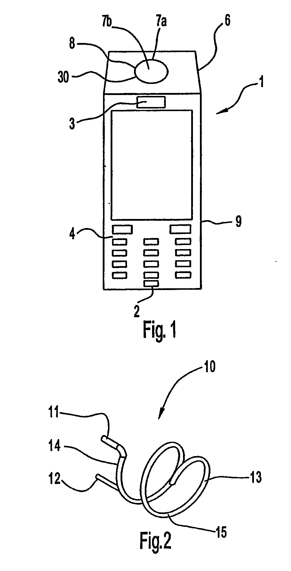
[0032]FIG. 1 illustrates a mobile radio terminal 1 according to the invention in which an antenna assembly is implemented. The mobile radio terminal 1 includes a housing 6 having a microphone 2, a speaker 3, a display 5, a keypad 4 which might be optional if the display 5 is touch-sensitive, a camera unit 7a, an antenna-lens-assembly 30 having an antenna 8 and an optical lens means 7b, and electronic circuits 9 inside the housing, such as a main controller, memory circuits, radio transceiver etc.

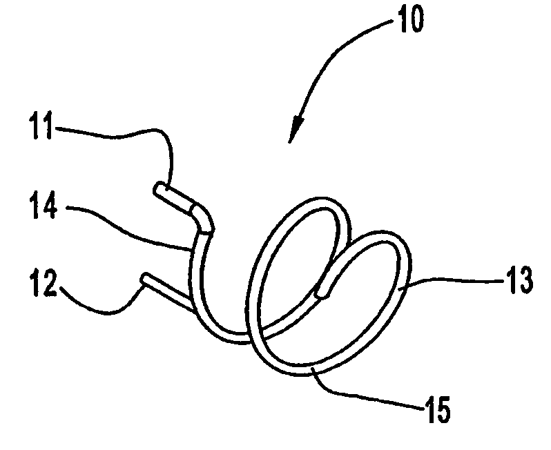
[0033]FIG. 2 shows a helical antenna 10 having an elongated conductor 13 arranged as a helix, forming a radiating element 15, wherein said elongated conductor 13 preferably has a length which is approximately one-quarter of a wavelength of a desired operating resonant frequency of the antenna. The operating frequency of the antenna for Bluetooth® or W-LAN is 2.4 GHz, for GSM at about 900 or 1800 MHz or for WCDMA (Wideband Code Division Multiple Access) at about 2000 MHz, but the helical ant...


PUM


Abstract

A mobile radio terminal in which a miniature antenna is integrated or spatially arranged with a camera lens. The mobile radio terminal includes a housing having a microphone, a speaker, a display, a keypad which might be optional if the display is touch-sensitive, and a camera. The antenna is arranged around a camera lens as an antenna-lens-assembly inside the housing in order to minimise space consumption, decrease hand-interference and minimise antenna losses.

Description

[0001] This application is a national phase filing of International Application No. PCT / EP03 / 04456, filed Apr. 28, 2003, which claims priority to U.S. Provisional Application No. 60 / 378,453, filed May 6, 2002, and to European Patent Application No. 02009866.1, filed May 2, 2002. TECHNICAL FIELD OF THE INVENTION [0002] The invention relates generally to radio communication systems and, in particular, to the design of built-in miniaturised antennas which allow compact electronic equipment to communicate. BACKGROUND OF THE INVENTION [0003] Compact electronic equipment is required to be compact in size, especially when portable. Therefore all components incorporated in portable electronic radio equipment have to fulfill this requirement. Furthermore the spatial arrangement of the components of the portable electronic radio equipment has to be as compact as possible due to the above requirement. Also, the components should not interfere with each other. As more features are integrated in...

Claims


Application Information

Patent Timeline
Patent Type & Authority Applications(United States)
IPC IPC(8): H01Q1/24H01Q1/36H01Q9/30
CPCH01Q1/242H01Q1/36H04B1/3877H01Q9/30H01Q1/362
Inventor YING, ZHINONG
Owner SONY ERICSSON MOBILE COMM AB
Why Eureka
Try Eureka